Dear friends, even today I am dealing with new problems with my health, so that I did not find the time to update this thread. I am now trying to continue for the second try. The first failed as I accidentally closed the window in my browser where I was working on it loosing everything! I will show you numerous pictures to hopefully make the reading of today's contribution entertaining!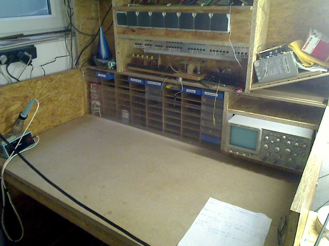
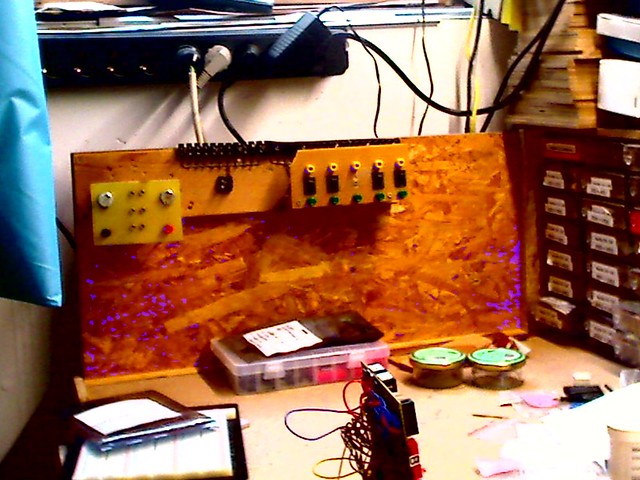
This picture shows my ultimate goal to have a well organized and empty workbench, here my electronic lab! Invisible on the picture at the top is the room where I have placed my modified PC 600W power supply from which I take the different voltage levels made available on my power bar, the aluminium bar you can see just below the raw of power sockets. I have made the experience that you never have enough power sockets!
Below the power bar there is empty space to place things at a well reachable distance while keeping the work surface empty! In this picture I had place the "power panel" there. Below this you can see shelves for assortment boxes for electronic components, far to few as they proved to be! To the right of it I have my oscilloscope integrated into the workbench. The exits for heat are hidden but well exposed to be able to dissipate the heat generated by the oscilloscope being active! On the left "wall" of the bench I have placed my soldering iron, just for the picture!
On the right side of my electronic workbench I have placed my phone so it is well accessible form both places.
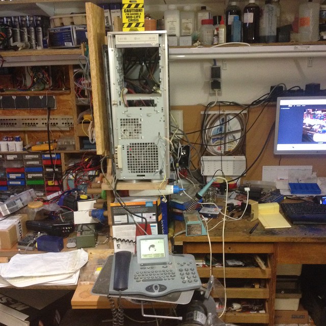
Here you can see a picture from today! It shows how my PC is placed between my "office and programming bench" and my electronics bench".
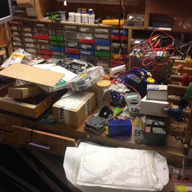
Sadly this picture shows that chaos is still governing the electronics workbench today!
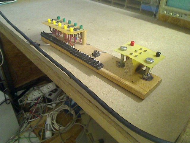
Lets continue! Here in detail my revision 1 of a panel I do use to connect the circuits I am "playing" with for learning to develop what I have in mind for my model "Carina" presented in another thread in this forum!
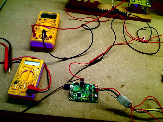
This picture shows an setup for experimenting. In my model Carina I do plan to install a lot of proprietary circuits to implement what I have in mind. This I will present later as part of my thread of building the model Carina from scratch in this forum! I do plan to implement a sheet control system for the sails of my model sailboat equivalent to the way it is done on the original sailboat Endeavour!

This requires the mechanics and electronics in my Carina to be able to change the length of the sheet by 8.3 meters. I do use as a winch a stepper motor. The electronics and the sensors allow me to ensure that the available length of the sheet is always just a bit more than what is actually required so the loose sheet problems cannot happen. The concept is relatively complex and unusual so that I will present it to you as part of the thread of building my Carina. But "experts" for sailboat models and experts from communities of physics have passionately expressed that it is not possible due to friction in the pulleys, model sailboat experts, and that there is no friction, physics experts! This created my wish to really verify who is right by modelling the sheet control system. For this I have to verify that models written by me actually reflect the reality. So I have to build experimental setups to generate real data and have this data made available for analysis in the Mathematica software from Wolfram. The technical terms for this are "HiL and SiL", "hardware-in-the-Loop" and "software-in the Loop". This techniques are finally reaching an adequate level of maturity in the Wolfram Software. Goal is to assign the data generated experimentally to mathematical symbols available within the Mathematica Software, as well as the "SystemModeler" software from the same source.
But to achieve this goal I had to acknowledge that in the 4 decades since I left university my mathematical, electronics and physics knowledge has dramatically eroded and that the advances relevant for my purpose in all 3 sciences have dramatically advanced. Thanks to so called "MOOC" courses from the best universities worldwide make it possible to study the topics for free by having videos of the lectures of professors giving the course, assistance's for completing the assignments and reading material. The fascination I felt studying made me perseverant to pursue this goals enough to fight against i.e. brain damages I got by my heart stopping to work once for too long! But as it is known, the brain is like a muscle. If you train it a lot the brain can reorganize itself to fix the consequences of brain damages. Basically my brain damages limit my ability to work concentrated over a longer period of time and not to store what I have learned once. So I always need a bit of time to refresh before being able to advance.
Remember, the goal of my activities in my hobby are not to complete a model, but being active building it and using it to get in touch with new areas that make me avid to learn more!
Lets continue! What I found out was, that in my experiment setups the cables began to look like a spider web! So my next step was to mount the panel on the "left wall" of my electronics bench:
But that was not enough! As my experiment setups require multiple electronic cards, see here a concept graphics of my electronic workshop:
This graphics allows you to get an impression about the whole electronics workshop I am setting up! You have me working on a PC on my office bench and communicating with RaspBerry Pi cards via WLAN. The local Raspi controls the microcontroller boards which themselves control i.e. a stepper motor controller. Remember that the winch in my model is build using a stepper motor. Magnetic angle sensors with up to 14 bits of resolution track the angle of the boom to the model center line so the software on the LPCXpresso board can compute the length of the sheet for that angle and have the stepper motor winch always adapt the sheet length to the length actually required. A second magnetic angle sensor tracks the "position of the sheet drum. So I do have on both control loops a "close loop" to ensure that no errors happen and if to fix them if they do. The actual desired angle of the boom is send from the R/C sender to the R/C receiver in the model, the position data is digitized by measuring the active state of the PWM data coming from the receiver. This data is used by my control system to ensure the sail does not open more that the user wants.
This revision 1 of the panel shown 2 pictures above was inadequate for my needs and the fun I have by usually exaggerating implementations made me start to work on a version 2 of that panel!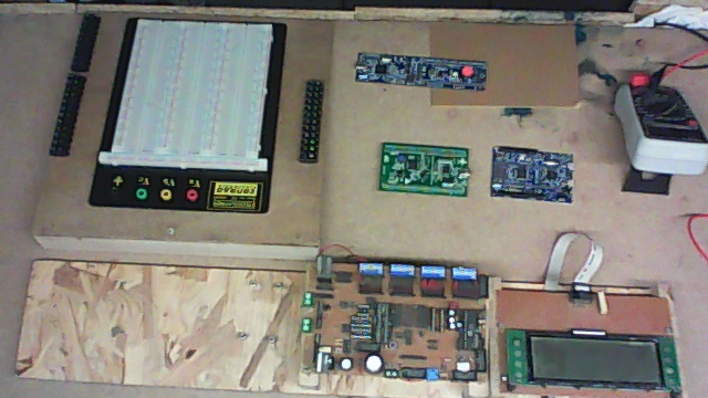 Before doing so here a picture that shows my concept to setup experiments! On the left I have a breadboard to implement "glue logic" to connect sensors and actuators, actuator is the term for any device that does something, a servo in R/C modelling i.e.! To the right you see that I would be using multiple controller boards for my experiments, which results in a need, of call it exaggerated wishes I do develop, to have a device that allows me to feed with energy multiple boards, to ensure each would be supplied as required by either 3 V DC or 5 V DC. Murphy's law say that the probability of something getting killed is higher the less availability for replacement parts or the higher the cost of a component. Chaos increases the probability of doing something wrong! At the bottom of the picture you an see my "experimental card" build years ago as part of a tutorial for enabling modellists to stop using electronics as a black box! by the way, it can be relatively simple to learn this!
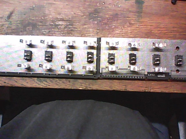
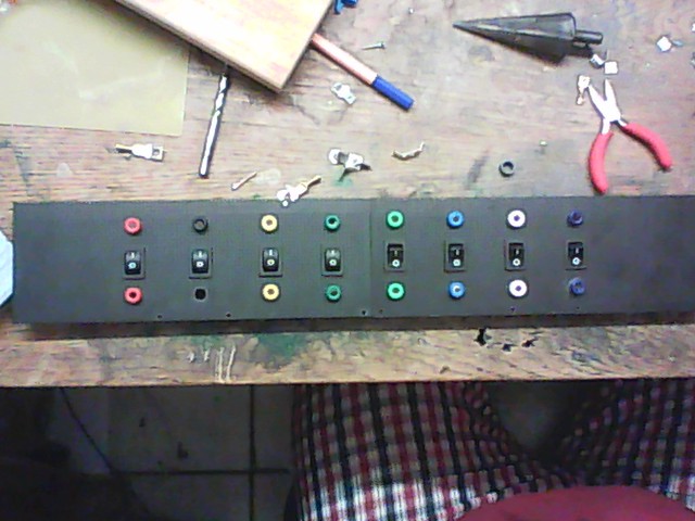 Here you can appreciate my revision 2 power panel in construction. I have made available with it 8 different voltage level, each with a socket in its own color following the coloring scheme used in PC power supplies. The panel sockets are feed with its corresponding positive pole voltage from below the panel surface. If you want to be able to switch each voltage ON/OFF individually you can connect your circuitry to the top socket, otherwise you can connect it to the lower one.
[size=78%]
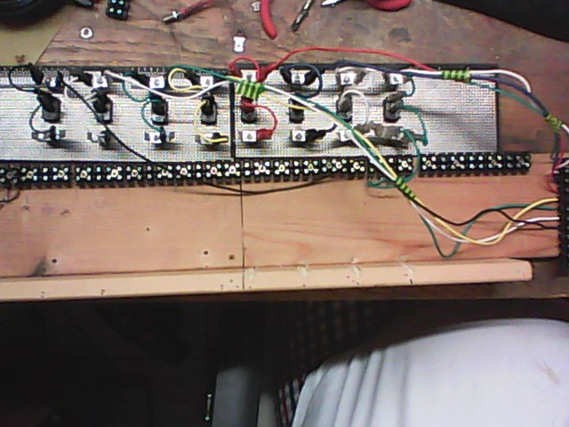
Here you can see the work in progress from the rear side of the panel.
Next a bit further down the road. Its getting more complex! But here as it was in the revision 1 version of the panel I have made available 5 screwable connectors for each voltage. The switch on the front side of the panels does switch them individually ON/OFF.
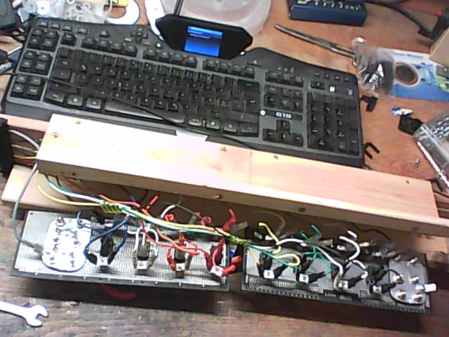
Next you see the completed implementation of the revision 2 panel before mounted in its final position:
Finally the panel mounted on the left side of my electronics workbench!
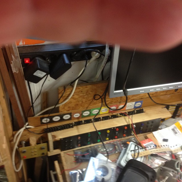
You can see that on the left side there is the part to connect the claws from a battery charger. As I might to be able to connect different voltages for the battery charger, the supply is connected via the 2 sockets on the front of the panel. To the very right side of the picture you can see a yet to be finished circuitry of fuses to the cables supplying the voltages to the panel. Above the panel surface you can now see the screwable connectors for each of the voltages, 5 for each, divided by a small wooden separator. While on the left side of those connectors you can see connectors for Ground, which are common to all voltages, above the panel those screwables, on the surface of the panel 6 banana sockets!
I do plan to have an color LED, called RGB LED's next to the interrupt switch of each voltage, which when the voltage is active, means available at its outputs, will be illuminated in the color of each voltage. Also I do plan to have electronic fuses to replace the short cables you see at the right side of the picture. Those will be made using MOSFET's, an electronic switch. I also do plan to have a RaspBerry Pi W, its latest version as of March 2017, which includes Bluetooth and WLAN wireless interfaces. The idea is to be able to monitor voltages and currents for each voltage individually and a software definable maximum current before the MOSFET switch interrupts the power supply to the panel, the electronic fuses! Her just the indication. Each RaspBerry Pi board can be controlled from my PC as if I had mouse, keyboard and display connected directly to the RaspBerry Pi board. The desktop of each RaspBerry Pi can be displayed and operated in its own window in the Windows 10 or Ubuntu OS on my PC!
This information makes it appropriate to report to you here another reason that delays me experiments. When I started to make myself familiar with the RaspBerry Pi boards and to learn the basics of Linux, the OS that operates on the Raspis it was relatively straight forward to communicate to the Raspi boards from my PC, to establish a link via an URL to each board and to program the boards from the PC by controlling the compiler running locally on the Raspi. Each Raspi got its own entry in a[/size]


 Author
Topic: Presenting my workshop and how I am fighting uphill to get order into it (Read 30967 times)
Author
Topic: Presenting my workshop and how I am fighting uphill to get order into it (Read 30967 times)