|
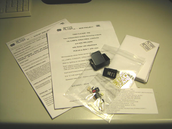
'TWIN FLICKER' (P90)
PCB kit with case
Two independent random flickering outputs adjustment of effect / rate
. |
|||||
|
|
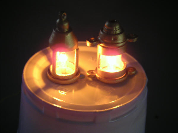
I've been asking for various bits of advice regarding building the Puffer on the forum, one question was how to make LED's look more like oil lamps that wouk be fitted to the mast. Riggers jumped up and said the ' Action make a "Twin Flicker" unit that simulates oil, open fire, candles or even Arc Welding!!!' Thanks Riggers.... as if it wasn't taking enough time and work to get the Puffer finished!!! ;-) I've build a few Action kits over the years and this makes the third unit / kit in this Puffer alone, the other two being the 'micro STEAM ENGINE SOUND’ micro size P64 on 4.8V to 6V receiver power. P64A PUFFER (single cyl) & the ‘UNIVERSAL’ TWIN LATCH 3 AMP RELAY SWITCHER (P44A), these I'll cover on another page. The kit is described
as:
|
||||
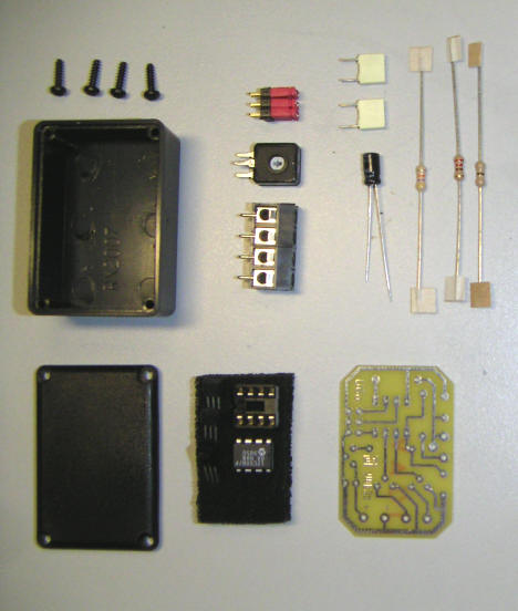 |
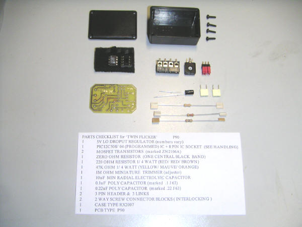
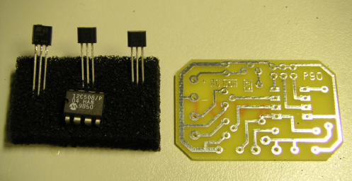
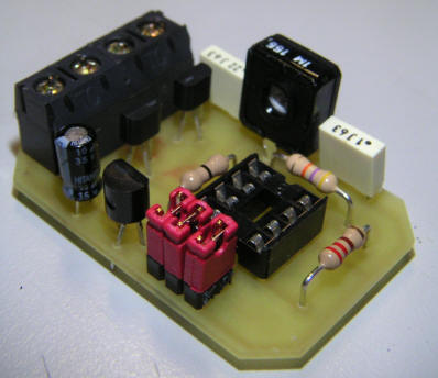
The kit is very simple, only 13 components.... the trick is in the PIC programmable IC. |
||||
 |
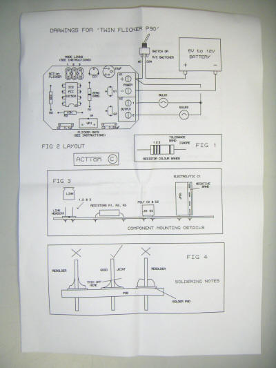
I'm not going to tell you how to build the kit, as Craig has written the simplest set of instructions that is possible to write! ANYONE that knows what a soldering iron is for can build this circuit........ BTW, you plug the soldering iron in, let it get hot, hold it by the end that doesn't burn you!!! | ||||
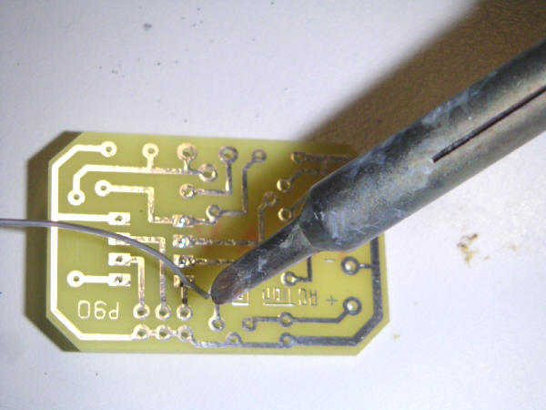 |
Tip 1:
Make sure your soldering iron
is CLEAN. |
||||
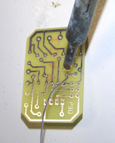 |
Tip 2: Put component in the hole, place solder on the joint, touch the joint & solder with the soldering iron. DON'T hold the soldering iron to long or let it get too hot...... practice & experience. |
||||
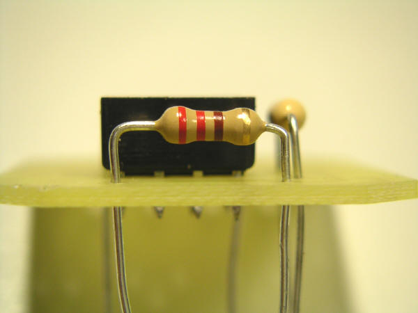 |
Tip 3: I leave a gap under components when possible; 1. If I have to take it out again, it's a bit easier. 2. I can clip on a multimeter if needs be. |
||||
 |
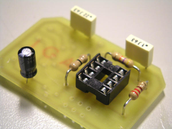
Tip 4: As a rule I fit IC sockets first then resistors, then diodes, then capacitors.... but always... it's only a rule! Cut the leas of components only after you have soldered them and you are fully satisfied it's in the right place. |
||||
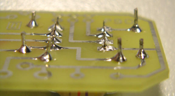 |
Tip 5: Trim leads low but not to the board while working on it. I will re-trim the leads once the circuit has been tested..... again it gives you one last chance to correct something. |
||||
 |
Tip 6: You can even leave a slight gap under the capacitors if you're clever like me! |
||||
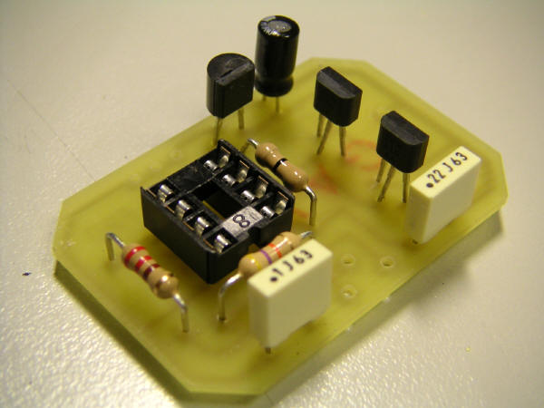 |
Transistors next...... get them the right way round. |
||||
  |
Everything in place..... except the IC. Remember, be careful, static can blow it up! |
||||
 |
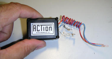
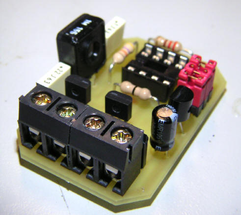
And this is what you
end up with! |
||||
 |
Get your batter out and prep some wires. Now before you connect anything to anything, go make yourself a cup of tea.... which allows you time to reflect on your building skills and also gives you time to remember anything you may have forgotten! Come back - CHECK & CHECK again! |
||||
 |
Tip 7: Get yourself a fully charge and hefty battery... if you're gonna blow it up, do it in style! |
||||
 |
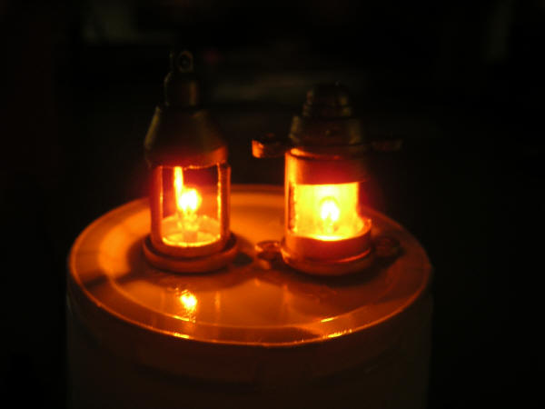
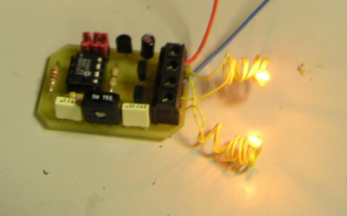
Mine worked perfect first time......... yes I was very surprised too! |
||||
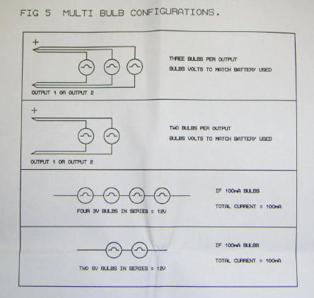  |
The unit can be configures several ways..... |
||||
|
And here are the video clips of it working. Excellent unit - 10/10 |
|||||
|
1.3 Meg |
4.2 Meg |
5.4 Meg |
2.6 Meg |
2.9 Meg |
7.4 Meg |
|
Excellent
unit - 10/10 |
|||||
|
|
|||||