|
Krick
- AVANTI -
Test bed boat! |
|
 |
|
Running name "PAM".
Semi-scale inshore shallow Vee race boat for electric for 540 electric
motor.
Kit cost (discontinued) ....£36
Accessories.. (motor, speed control & batteries) + radio.
AIMS
I selected this kit on the basis of it's good looks alone. I already had
two other electric boats, the
MFA PIRANHA and the
Graupner HYDROSPEED,
the latter was much faster so I wanted another boat to match it. In a
couple of model boat books boats very similar to the AVANTI are used in
electric competition races and as the AVANTI looked fast on the box's lid I bought
one! |
|
STYLE
The hull is a very shallow vee with a racing deck and cockpit. The top
cowling could almost pass as a tunnel hull as the two are very similar
in appearance, which first gave the idea for the outboard motor. In the
model world this type of deck also serves as a self righting mechanism (SReMECH
ala Robot Wars). This type of boat is seldom seen these days but is
a predecessor of today's tunnel hull racing boat. Inshore racing tunnel
boats are designed
for outboard engines, high acceleration and possess phenomenal cornering. Lets
see how the model matches up to the real thing.
I've built and rebuilt this kit five times in five different
configurations,
which are:
Mk I Electric outboard, 10 Cells.
Mk II 1.7cc IC engine.
Mk III Electric inboard, 10 Cells.
Mk IV Electric inboard with gearbox 10 cells.
Mk V 2.5cc IC engine with Airscrew.
|
|
THE MODEL
The kit is all ABS and will therefore produces a boat that is light and
strong. The boat is quite small at 620 x 200mm but ideal for the designed
electric set-up. There are three main
parts to this kit, the hull deck and cowling or canopy as referred to by
the plans and was a relatively simple kit to build. The plan showed all details clearly
laid out, it even gives two internal layouts for 7 or 10 cells.
Use only Stabilit Express or Devcon 'Plastic Weld' two part epoxy or a good Superglue during
construction of an ABS boat. Although I did silly things to the boat
construction can only take a few hours if I had stuck to the plans.
|
 |
|
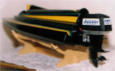
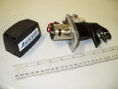
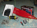
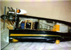
PAM Mk I
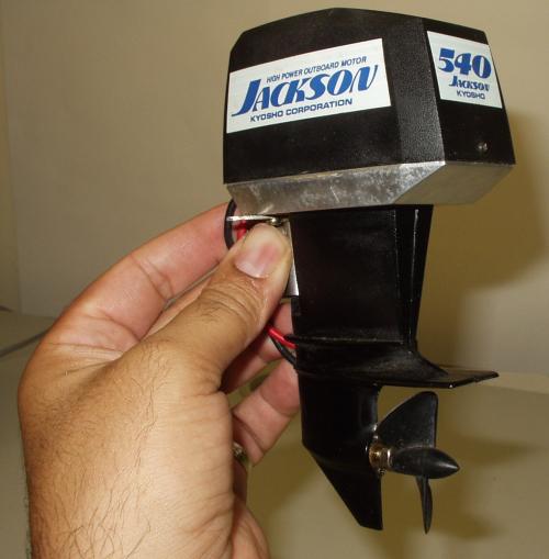
The plans showed the motor set-up of a 540 motor driving a submerged
propeller, my initial plan was to build the boat with an electric outboard
engine hanging on the back. Graupner, Kyosho & Robbe all make electric
outboard units incorporating 540 motors, I bought the Robbe / Kyosho
'Jackson' outboard as it was the cheapest.
As I was intending to do strange things at the back, the transom would
need strengthening in a big way. But how do you strengthen a wedge
shape gap to make it strong enough to take through bolts?!? After a bit of head scratching the answer came while sanding down
car body filler on another boat, 'this is hard work' I
thought, 'this stuff has dried as hard as concrete', and there was my
answer.
The inner surfaces
were first reinforced with 2mm ply and glued with Stabalit to stop the
ABS tearing. I then filled the gap between
the inner and outer transom with 'Isopon', car body filler which was
compacted as much as possible. The cured filler allows the bolts holding on the outboard
on to be tightened on to it without crumbling. Looking back, this was
the only ideas I had that actually worked on this boat!
The hull and deck components form an airtight compartment for buoyancy,
but for extra safety, put in some polystyrene blocks in the voids just
in case. The hull to deck joint is a little different
compared other ABS kits, the joint is a flange type and will end up below
the water-line so it must be made extremely carefully to prevent leaks.
As the joint is a little tricky to get right, use liberal amounts of
Stabilit after making SEVERAL trial fittings. Clamp together with
clothes pegs or bulldog clips when you're happy. I used too little glue in
the joint and mine started to leak after a few outings. (To rectify this I
inserted a knife into the split and opened it up until I found where
the joint was solid again. A flat needle file was used to remove the
old glue and then cleaned up with meths and a good strong batch of
Stabilit was liberally stuffed in. The repair wasn't to hard but it's easier to make the
joint properly in the first place.)
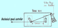
The internal plywood bulkhead was moved forwards
to 150mm forward of the transom to allow the radio box first used in
the
SHG SHADOW to fit directly into the AVANTI. A frame of 9mm
wood surrounds the radio box making a snug fit only needing a rubber
band to hold it down. The radio box leaked in here the
same as it did in the SHADOW, I never could make this box waterproof.....
With the hull complete I looked at the top. The cockpit was a little
bare - a Koala bear actually! - Get it? - A little bear?.... All right I'll forget
the jokes. A drivers head was bought from the model shop, it's from a
electric car kit and is roughly the right scale. A body was carved from
balsa one evening in front of the TV when nothing much was on as usual.
When I had finished, I put plasters on all my cut fingers and was chased
out of the living room when the Mrs saw the wood shavings over the
carpet. The body was screwed to the cockpit and the head screwed
to the body, Stabalit fills the gaps and secures it. A face was
painted on in the avant-garde style, avant-garde-a-clue more like.
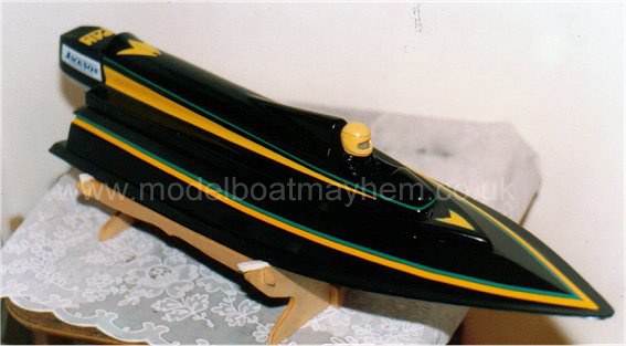
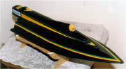
I finished the boat in gloss black using car spray paint, trimmed with
yellow and green lines then 'Tufcoat' to protect it. The colour choice was in
honour of the Jamaican bobsled team that gave us such a laugh in the
winter Olympics a few years ago by coming down the run on their heads!!
Well done lads it was a great effort especially as some of them had never
seen snow before!
|

|
|
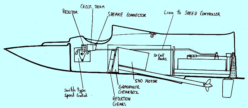
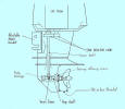
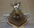
I now started to diverge from the plan by installing an electric
outboard motor. The Jackson outboard is available in two sizes, 380 or
540, the only differences between the two is the motor size
and the size of the prop. I bought the 540 for the extra power. The
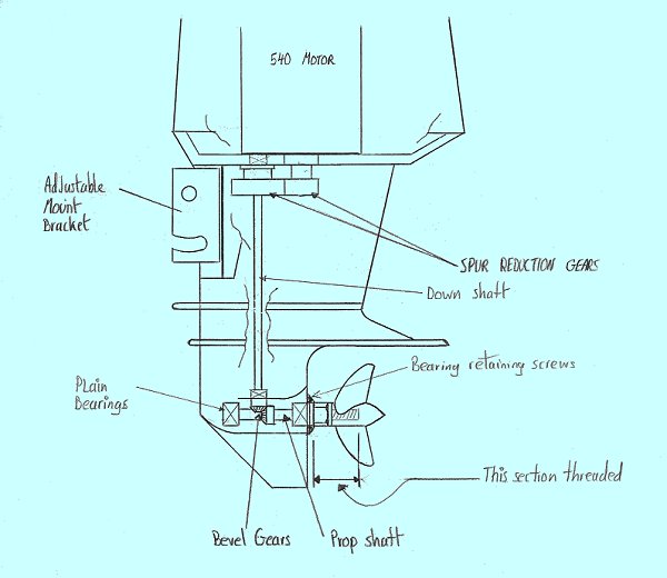
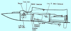
outboard is all metal apart from the cowling and thus quite heavy. The
drive line consists of metal spur gear reduction from the motor to the
main vertical shaft and then metal bevel gears turn the drive at right
angels for the final shaft to the propeller (fig a). I had found out the
hard way that propeller size is very important and a new boat might need
changing three or four times before you get one that works well. The
Jackson has a dog drive fitting for the prop but I didn't have any of these
types of prop so the shaft was cut down and a 2BA thread cut on to
allow me to use ordinary propellers of which I have many.
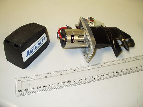
One of the first thing I do with anything I buy is to strip it down to
see how it works and the quality of the product. My mum always used to
tell me off for this when I was a kid but now I get paid for doing it as I
repair computers for a living and generally people like them to work
again after I've pulled them apart so I've learned how to put them back
together again so they still work!. If you do strip the outboard down,
lubricate liberally with Teflon or `PTFE' grease. The outboard can be run
in by connecting up a low voltage of say
3 or 4v. |
 |
|
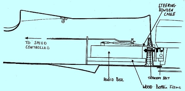
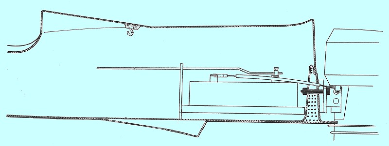
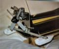
A square was cut from 3mm ply to match the outboard's fixing plate and is
used as a spacer to give the tiller arm more room to move. The
unit was held on with long M3 Allen screws that passed right through the
outboard, transom, an inner reinforcing brass plate and secured with nuts
inside the boat. The outboard was positioned so the anti-cavatation
plate just level with the bottom of the hull. Steering is via two
Bowden cables from the forward servo to the outboard tiller arm. Because
of the short length of cable, it was sufficient to drill a hole
through the transom and use Superglue to hold the outer plastic tube, no
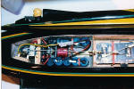
further support was needed. A
coil type speed controller was fitted to the
ply bulkhead and a link taken aft to the aft servo. Lubricate the wiper
contact with silicon grease to help prevent arcing. A beam of wood
bridged the compartment at the front to support a set of speaker
connectors to hook up the batteries as I was still using the cell packs I
had made up for the
PIRANHA and
HYDROSPEED. The main cells were fitted
as far forward as possible to keep some sort of balance in the boat as
the boat was becoming very tail heavy.
I may be describing this a simplistically but it took ages to guess where
everything should go as I only external pictures of racing mono hulls
with an outboard engine. As I didn't have a prototype to model it off,
I decided to go for aesthetics and build it so that it looked good. Well it looks good to me!
|
 |
|
SAILING Mk I.
Down at the lake, things were still looking good. With the boat (now
named PAM to please the misses), sat on a stand, the batteries were
connected and wedged in with foam plastic. A X40 propeller was fitted to
the outboard motor,
the radio checked and the boat placed on the lake. The boat sat low at
the stern due to the weight of the outboard. Hopefully as soon as the
boat got on the plain this would no longer be a problem.
There now comes the moment that all modellers most look forward to and
dread at the same time -how will it perform? You can make all the calculations
you want but it's only when you hit the accelerator that you'll find out
how good she is. I opened up the throttle full - if the boat is
going to do something spectacular, I want it to happen straight away
and get it over and done with. The motor started up and we were off...
Well, had hoped that the boat would leap out of the water and fly at a
low attitude across the water but it didn't........ It sort of whined, revved a
lot, swaggered around a bit and moved off slowly forward with the bows high in
the air. It was working but the words "electrifying performance" didn't
immediately spring to mind. The boat seemed to be trying to go but
despite my careful draughtsmanship and precise computations, taking
into account Newtons laws of motion, Einstein's theory of relativity, and
a hearty breakfast, the
performance was rubbish!
Everyone needs a motto to work by, mine is "If it looks good, it must
work good". (OK so it's not good English, but it's not an motto for
speaking English!). My motto is borrowed from Jack White of Harrow
college of higher education who tried to teach me basic mechanical
engineering many years ago. He was a great mentor to me in an
engineering sort of way, thanks Jack.
Most successful designs mostly
seem to have simple, clean lines and mechanisms like Concord,
suspension bridges and sea sharks 'all look good' and work well, but
although my boat looked good, my lack of applying elementary boat
building principles made the boat under-powered and tail heavy.
At first I didn't think the balance problem was too serious and pressed on
regardless hoping that I could increase the power enough to get the boat
on the plane. All sorts propellers and adjustments were tried but the best
performance I could attain would be best described 'lame duck'.
Back home on the work bench, I looked very critically at my modifications.
The Kyosho Casablanca boat uses two Jackson outboards and that works
fine. The Casablanca uses the outboards in surface drive mode but
with the outboard so low in the water on my model, the propeller had no
chance of breaking the surface. I had allowed room for the outboard
to be moved up and down which was soon done but a new hole had to be
drilled for the steering cables, the old holes being filled with Stabilit.
I managed to raise the motor unit by 18mm, the length of the slots in the
bracket. I also fitted a better car racing motor in outboard to increase
the power. after leaving the new motor and unit to run in for a couple of
hours she was ready for more sea trials by the next weekend.
|
|
|
|
SAILING Mk I again.
The improvement was hardly noticeable even with all sorts of different props.
After a long while of tweaking this and that I noticed the hull was
starting to sit very low in the water and decided to bring it in
for investigation, I put the boat into reverse and the propeller
promptly unscrewed itself and fell off. "Blast!" I had forgotten to
tighten the nut on the propeller. The boat slowly drifted out across
and down into the lake. This subsequently turned out to be due to the split in the join I
described earlier. I was glad of the polystyrene buoyancy fitted which kept
the boat from going totally under but only just. I eventually recovered
the boat and the radio room was completely flooded and required the replacement
of a
servo but the rest survived. Everything was rectified and I
persisted with a few more outing but with no more success. A snap decision was made and the
whole idea was shelved. "Why did I chicken out so quickly?" When you
know you are beaten in chess, sometimes it's better to give in and
start a new game, ( that almost sounds intelligent!!! - sorry about
that!). |
|
PAM Mk II
About 3 months later after building another model I started thinking
about the AVANTI again. I had bought a second-hand HP12 IC engine that was going
to be used in a later model but I thought it could be utilized here. Well
I knew that an IC powered ABS hull could work (Graupner ARROW), so maybe
I could do the same again, but this time without the help of a
tested design.
|
 |
|
Back in dry dock
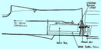
A small flat aluminium plate was made up to mount the engine and to fit
the front end of the battery compartment. Even with the aircraft type
silencer fitted to the engine, there was still enough room to enable the
engine to line up with original shaft position on the plans. The glow
plug sat about 85mm from the font wall. The plate sat on two wooden
blocks. Liberal amounts Stabilit was used to hold the wood bearers down and then loads more was
spread around just to make sure, Stabilit was the only thing that was
holding the engine down. A couple of self taping screws held the plate
on the two wooden blocks. I hadn't removed the skeg from the bottom of
the hull during initial building and this proved useful. The kit came with
a shaft and this had brass bearings so it was good enough to fit in
place with a HUCO plastic universal coupling. (Shafts with plastic bearings are to
be avoided no matter what the application due to there poor durability and
high friction).
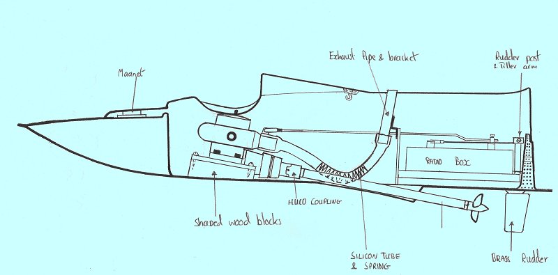
A small blue SLEC tank was fitted in between the shaft and side wall
and wedged in with Polystyrene.
What to do with the exhaust presented a real challenge. I don't like just
throwing the exhaust over the side in a non-scale manor, I like to throw
it out the stern where it looks like it's helping to push the boat along.
To run the exhaust out the transom was too difficult in this boat and
going through the side would mean breaking the integrity of the air tight
compartment so I started to look upward. Due to the cowling's
design I couldn't fit anything to it permanently because it's has to
be lifted to gain access to the interior. I decided to fit a short
length of 10mm brass pipe to a spare Meccano bracket on the middle
bulkhead and arranged to protrude out of top of a new hole in the middle
the cowling. Silicon tubing of suitable size connected the two
together. This tube tended to kink due to the sharp angle it had to
turn so a couple of 10mm springs were forced along the silicon which
kept the tube open.
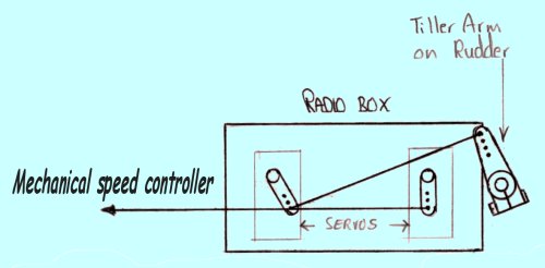
A small brass rudder and the rudder shaft taken up through the radio box
frame and over the top of the radio box and a single arm tiller fitted to
the top above a suitable spacer. The tiller arm was a tight fit but I
managed to get it in after a little jiggling about. A water pick-up was
made from small bore brass tubing and a hole drilled 15mm left of the
rudder. The speed controller was obliviously removed and a longer
link made to connect up the servo to the carb. I fitted hinges and
magnet to the cupper cowling, the same as on the
Hydrospeed, the magnet fits under the drivers dashboard
to hold the front down. Not very practical but nothing showed on the
outside!
|
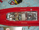
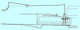
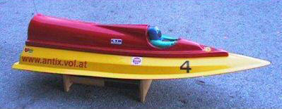
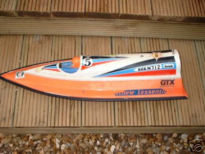
Not Mine but some else had the same idea with the IC
engine!
( Found on eBay ) |
|
SAILING Mk II.
So far so good. At the lake a silly oversight came to my attention as
soon as I started the engine up. The exhaust was pointing upward and as I
was looking down on the boat to start it, I quickly got a new hairdo just
before I dropped everything on the jetty while wildly rubbing my eyes.
After a couple of tries i learned to start the engine while leaning way
off to one side...... is that what's called stand-off scale?
The engine was very hard to start at first but eventually got going and
needed very deft adjustment to get it running smoothly. I put in the water
and let go. Well it did work, but again I wasn't impressed! Slow
plodding runs, nothing like the "scared cat" speed I wanted.
Because I had been spoilt by the success of the
Arrow,
I was expecting a much better turn of speed from such a light / small boat
with an IC engine but this was not the case.
My usual
plan for poor performance boats swung into operation, try every prop in
the box, adjust the mixture from lean to rich and back again, change the
fuel, change the plug, etc. etc. The best speed I got was respectable for
an electric boat but at least it was riding the water at the right
attitude with it's nose slightly up. Trouble was the engine kept stalling
in a similar way to the Arrow but by now I was on my smallest prop,
a P35 and it still didn't have enough power to turn it. Maybe the engine
needed more running in.
Back home I removed the engine from the boat and was soon annoying the
neighbours by running the engine in with an air prop late into the
evening. After a few tanks of fuel the engine was as ticking over much
better and now seemed quite powerful. The engine was fitted back in the
boat and so back down to the lake but only a very marginal performance
increase was noted. It would run well for a short time then conk out.
I got
bored of this very quickly and came to the conclusion that the AVANTI
wasn't going to be successful in this mode either, promptly gave up and
retired the boat....anyway I was fed up with getting a face full of
exhaust every time I started it up. It was just as well I
gave up because when I got home I found out that the motor had started to
a tear free from the ABS floor. It had fractured partly from oil, heat,
fuel etc. but mainly because of the load of pulling on the starter belt in
rather an exuberant manor!
it.
The epitaph to the MkII was I never tried scale type props with lower
pitch angle on the blades which might have worked. Also because of the
large skeg a small 35mm prop might not have been getting enough 'clear'
water to bite into thus with increasing speed would cause different engine
loading problems which can't be checked while the boat is stationary. A
larger but shallower pitch three bladed prop might have a better bet as
more of the prop would be in clear water. I'm just guessing here but
that's what I'm best at!
|
|
PAM
Mk III
After completion of yet another boat kit, curiosity got the better of me
again and I returned to the AVANTI, such a nice looking boat MUST be must
be able to run well. I took the plans into the study and scanned the plans
carefully. The plans showed the boat should run on a 540 motor with a
straight shaft and submerged propeller, so as my plans had failed I would
try following the instructions. I pulled the chain and left the study.
Dry Dock Again
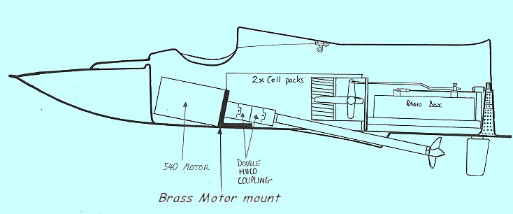
The compartment floor was repaired with off cuts of ABS and a brass motor
mount was made. A standard 540 motor was fitted with double HUCO couplings
down to the shaft fitted in the Mk II stage. The original speed controller
was refitted and the motor connected up to 2x5 cells (12v). Getting the
batteries and motor was a bit of a squeeze but I got it all in eventually.
The rebuild didn't take very long, that's one reason that made me keep
coming back to this boat, new ideas could be incorporated without too much
difficulty. |
 |
|
SAILING Mk III.
Running was very mediocre, about the same as the Mk II but quieter.
The boat got on the plane but was not flying over the water, it seemed
under powered. I still wanted a more speed and thought it must possible
without fitting loads of batteries or expensive motors. After all the
Hydrospeed worked well with it's surface drive, single motor and 10 cells.
I now had the same amount of power but the speed was nowhere near the
same. I wanted to fit a strudder but the radio compartment layout
prevented me running a shaft to the transom without major surgery, so that
was out. I kept the boat in the Mk III format for a few months while I
worked on different projects and a summer building break. I had spent so
much time on the boat that I couldn't remember my wife's name so spending
more time with her was in order as I can't afford a devoice..... I might
loose my boats!
|
|
PAM Mk IV
One week later, not really. After a while I decided against the better
judgment of myself and wife to have another go at the AVANTI. She
actually said "Not that stupid thing again!" But I could see through
her reasoning and she actually was goading me to persist with the boat!!!
I've read that an electric motor likes to 'unload'. Now I should know
what that means seeing as I've got an 'O' level in physics ..... but . 'Trial & Error'
will have to suffice. Anyway according to some
books, electric motors become more efficient the higher they are
allowed to rev e.g. a motor might take 10 amps to rev at 10,000 rpm, but
only 15 amps to rev at 20,000 rpm. I'm not sure how technically correct
but you get the general idea.
There are two ways to increase the rpm from a given motor;
1 - use
small or fine pitch racing propellers, or
2 - use a gearbox.
Small or
fine pitch racing props are not made by anyone at the time and would
be very in efficient anyway. I went out and bought a 3-1 Graupner gearbox
as used in my
Graupner Hydrospeed.
|
 |
|
RECALLED TO THE DRY DOCK
Fortunately the gear box comes with a set of reducing bushes to cater for
different size shafts, one almost fitted and only needed a little help.
The gearbox was secured to the shaft fitted for the IC so that the gearbox
could sit on the floor without any packing.
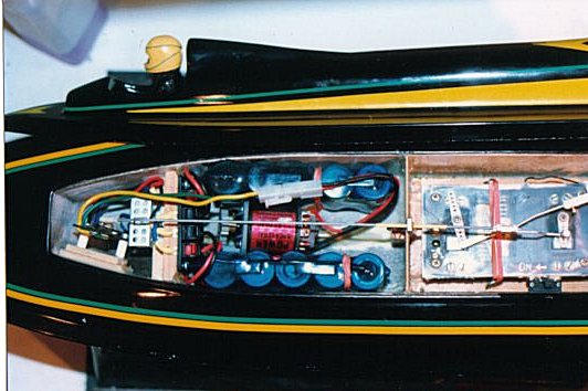
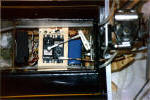
A cross beam at the front was refitted and supported the speaker
connector and the resister for the wiper type speed
controller, again as used in model cars. I tried a wiper
resister controller this time to see how they compare to resister coil
types, (coil types tend to drain the batteries if not returned to dead
centre every time and get Very Hot!). A long tenuous link connected the controller to
the rear servo through a steadying brace. As you can see with the
gearbox, batteries and controller it was a very tight fit at the front end
but the boat was now in balance. The set-up was left to bed-in over night
on a low voltage.
|
 |
|
SAILING Mk IV
At last a much better performance, the boat was getting on the plane
without difficulty but the boat still seemed to be hiding it's full
potential. It wasn't as fast as my
HYDROSPEED but could out pace with my
PIRANHA. I kept the AVANTI in this mode for quite a few months as I
thought it was good as it was going to get. ............ I again changed my mind
after a short while, but what now?
|
|
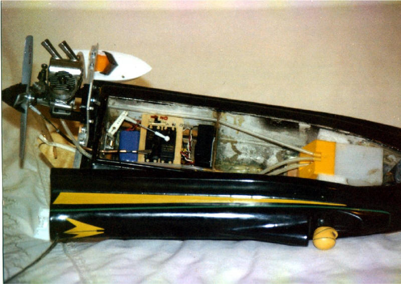
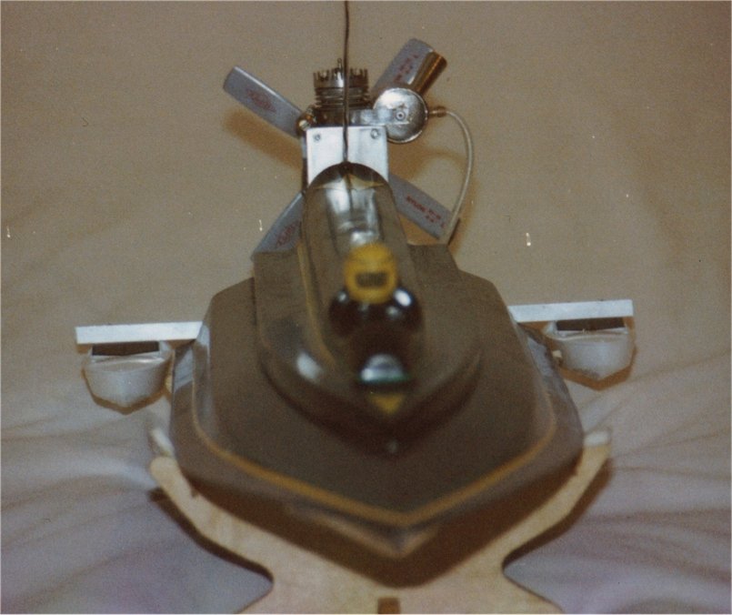
PAM Mk V
I had now decided that the AVANTI was teasing me in that I suspected that
if I could find the right set-up I would be able to get the speed I
wanted. During the summer I saw an air boat down the local lake and
although it was unstable and hard to control the speed was really impressive!
Anything that moved quickly impressed me when compared to my AVANTI.
An
air boat is usually a flat bottom style with an air propeller at the back
and air rudders behind the prop. As nothing but the smooth hull of the
boat is in the water they are used to skip over weed, muddy and shallow
waters. Back home I dug deep down into a few old boxes and found an OS15
aero-engine and propellers that I had forgotten about.
|
   |
|
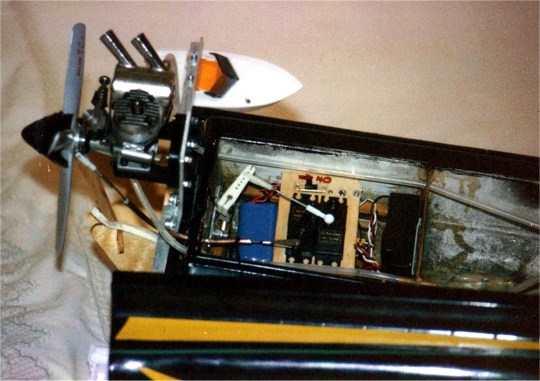
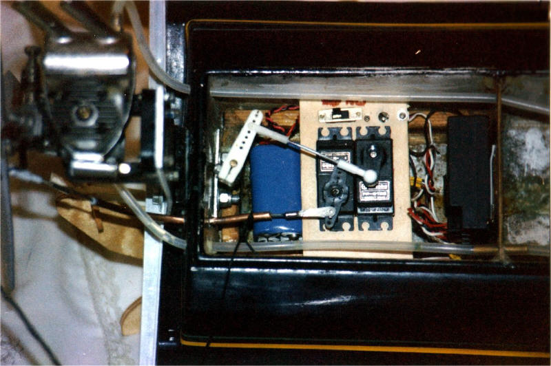
RADICAL REFIT IN DRY DOCK
I gave up on the Tandy radio box idea as it was leaking more than a
cabinet of MPs and made up a ply platform to mount the servos. The
batteries and receiver was stuck in any convenient spot . I wasn't
too worried if the radio got a little wet as I had a sneaky feeling I
wouldn't be keeping the AVANTI in this mode very long.
The rudder was still in place and the water pick-up that had already been removed
in the Mk III electric version. A yellow SLEC tank was fitted as far
forward as possible inside the hull and two fuel lines run out through
the transom, one for the engine feed and the other to pressurize the
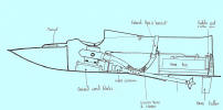
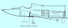
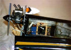
tank from the exhaust pipe as the fuel would have a long journey up to the carb. A long
aluminium engine plate was cut and shaped as shown in the photo. A ply
square wedge is sandwiched between the transom to allow clearance for the
engine mount bolts. The engine itself is bolted to a standard plastic
aeroplane mount. The throttle is controlled by a Bowden cable in a 1/8
brass pipe taken through the transom. The silencer in a Mardave car
silencer modified to take a hose-clip type clamp to hold it on around the
engine, any gaps were filled with 24 hour Aradite. The smallest
'pusher' propeller for this size engine was meant to be a 8x6 which
would leave a lot of the propeller below the water line so it was
slightly adjusted by removing the tips with a hacksaw and then
checked for balance. This set-up looked rather weird but I had high hopes
for it. The AVANTI now looked like a cross between a motorbike and a
dragest! But would it work? |
|
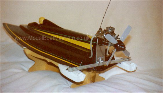
SAILING Mk V
The engine started up with some difficulty due to the height of the
engine above the tank but I got it going in the end. I ran the engine till
warm on the boat stand and everything looked good. While running the
engine up to speed it started to push the boat and stand across the
jetty, this reassured me that there would be enough power. I put the
boat carefully on the lake ...............Whoosh!
Water sprayed up in all directions
completely covering me, the jetty and anything else in a 5 meter radius!
The boat shot forward a few feet before
staling! Failed again.
The fault seemed due to the fact the back still
didn't have enough buoyancy to support the weight of the engine and hold
the propeller up out of the water which was the original problem I had
with the Mk I version.
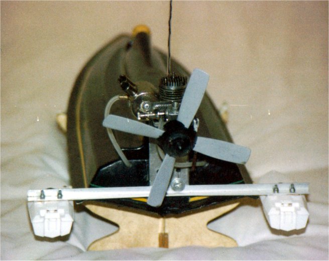
I re-drilled the engine plate and managed to raise the propeller by
another 15mm. I couldn't find a smaller pusher propeller so I bought
another prop of the same size and milled out half of the two centre
sections with a flat electric wood drill bit so that when placed
together I had a four bladed propeller. About 40 - 50mm could then be
cut of the end of each blade, smoothed of and the whole thing rebalanced
and still retain roughly the same blade area!?!?! The new hub was then
glued with Stabilit to provide a little more strength and clamped
together on the engine shaft. It fact
Mike Elson of the Peterborough Model Centre almost passed out when I told
him what I had done. I like Mike he's a helpful sort of bloke if
not a little jumpy because his greater experience!
In all I gained about an extra 50mm under the tip of the propeller. I
went down to the lake on the next weekend and waited till nobody was
about. I was extremely cautious when starting the engine with the new
propeller, Mike had put the frighteners on me. So for safety reasons I
planed to start the boat from inside the car with all windows closed
and the doors locked but my arms weren't long enough to reach the boat
on jetty. feeling brave I got out of the car to start her up in a more
conventional manor. Once the engine was started up, the propeller seemed steady
enough with no noticeable vibrations.
On the lake the 50mm didn't prove enough. I was again covered in a huge
amount of high speed spray much to the delight of people that had sneaked up
behind me while I wasn't looking. I said 'It was meant to that!' but I
didn't fool anyone. This was captured on video much to my continual
embarrassment.
I needed more height at the transom, I know I'll fit floats. I took a
trip to a large toy shop with a letter the wrong way round and bought two
small toy boats. Now this is a really silly idea, but then again an air
drive IC engine on a shallow vee boat was a silly idea. I tried it again at the
lake, the propeller was still too low and I got a third drenching. Not
the best way to get a bath.
|
|
    |
|
CONCLUSIONS
Well I eventually gave up on PAM, the boat not my wife! It was been striped down to the bear
hull and put in storage awaiting further development. The AVANTI
has been a disappointment to me as it didn't live up to the speed it's
looks promised and never proved faster than an average electric boat.
Don't get me wrong, I not saying it doesn't work, it does what the makers
say it will do but I was after much more and I will get it one day! It did
look good with the Jackson electric outboard on though.
I should have fitted surface drive to the boat with a long shaft to the transom
before giving up.... but then again I already had this set up in my
Hydrospeed. But I could have tried an IC engine!!!!! I might do it one of these
days, watch this space.
If you have built one of these boats I like to here how you
got on. |
 |
PERSONAL RATINGS (out of 10)
Value ................................. 7 (Comes with usable running
gear)
Kit Quality ......................... 8 (Clean, sharp mouldings)
Kit Design......................... 5 (Good appearance, questionable
performance)
Ease of Building .............. 8 (Goes together easy enough)
Finished appearance ..... 7 (Good but needs good paint job)
Handling ........................... 5 (Nothing spectacular)
Next .......
All the boats I've built so far have been on the small size with a maximum
engine size of 6.5cc so how about a big, mean off-shore machine, the
Hydrafibre ATLANTOR sounds good, it needs a 10cc engine! |
|
"Well all of this
is just my opinion, but what do I know!"
|
|
|