I will be totally honest, as I am always trying to be! I have the StepRocker card not behaving like I was used to and so i am investigating this.
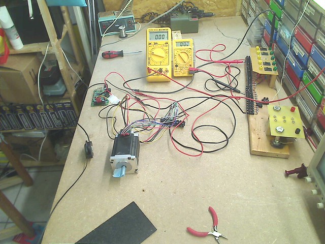
In this picture you can see the setup i have made in my brand new electronics working desk. To the right you see the unit that allows me to connect fixing with screws the cables and measurement equipment to the power supply. It also has a total of 5 small switches which allow me to switch on and off up to 5 different voltages, those are the black stuff between the yellow and the green banana jacks on the rear board. Just for completeness, the board in the front of this unit has to large screws to which I can feed the desired voltage to connect the battery charger!
In the middle back of the picture are to multimeters, the large one to the right is connected in series to the positive pole of the power supply of the StepRocker board and set to measure current up to 10 A! The smaller one to the right is connected to the power supply unit to indicate the voltage applied to the StepRocker board.
To the left, a bit in front of the multimeters is the StepRocker board and to the right of the board is the connector, to which i connect the stepper motor. This way i can replace the stepper motors relatively easily! A stepper motor with 8 connecting cables offers the user another possibility and i do use this opportunity to introduce you to it! Remember always to cables, a pair, will show a very low resistance when measured with the Ohmmeter, demonstrating this way that they belong to one set of coils. So having 8 cables, means that I do have 4 set of coils in the stepper motor. This means that i have to connect them in a way to reduce the number of cables to 4, as this is the number of cables that can be connected to the any stepper motor controller. it is now posible to connect the coils in 2 different ways. You can either connect them in series, what means that you connect 2 coils by connecting one cable from each to the other, the Ohmmeter will show twice the resistance as now the resistance would be measured of the cable that make up both coils. The other way is to connect them in parallel, this means connecting 2 pairs of cables coming from 2 coils in such a way to the stepper motor controller that they end up being connected in parallel to the same 2 ports of the 4 of the controller:
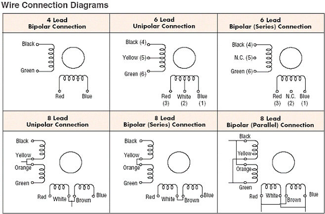
I am using this picture, as it shows the diagram of a stepper motor with 2 pairs of coils, but is intended for another message! At the poles of the coils you see colors named, which allow to identify the right cables. Lets take the diagram in the second row lo the left. here you see the coils connected in series, so the the stepper motor controller we just connect "black" and "green" ones and the "red" and "blue" ones to the motor and connect the left cables as shown in the graph.
To connect the coils in parallel we would connect the "black" and the "Orange" ones to one jack of the controller, the "yellow" and "green" one to the next, "red" and "brown" and "white" and brown" finally to the 4th connector.
What is the difference? Well. connecting the in series gives you a bit more torque, connecting in parallel makes the signals more stable and in consequence the stepper motor will operate a bit smoother and in consequence be able to be operated a bit faster. You find this graph or the relation of the colored cables to the coils in the datasheet of your stepper motor. If you do not find a datasheet you might guess the right pairing by test and failure. Should you fail to connect them in a way that the pairing of the coils is as shown in the picture you will notice a problem when trying to operate the stepper motor. One additional piece of information that might help you to solve problems you might face when trying to operate your stepper motor. That is definitely one of the purposes of this tutorial!
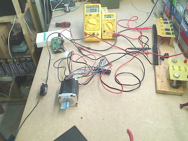
Now I have activated the switch applying the power supply to the StepRocker. The current reading shows 0.08 or 80 mA and the tension reading 26.1 volt!
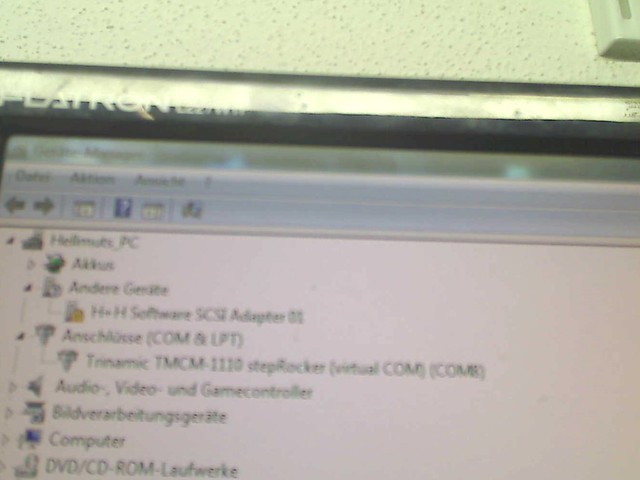
Then I go to the Windows Device Manager to verify the StepRocker board has been identified correctly and assigned to which COM, here COM 8! The reason for this is that I first had huge problems to install the driver. It actually made my 2 PCs inoperative until i found out how to deinstall the driver. The reason is that if you try to install the driver LIBUSB the normal way it will replace all drivers in all USB ports so that everything connected to USB stops working! A year later finally a filter was made available that allows to assign just the port desired the LIBUSB driver by using a software filter that is part of the download when the latest version of LIBUSB is downloaded. So, please, be cautious and better ask twice for support to make it right!
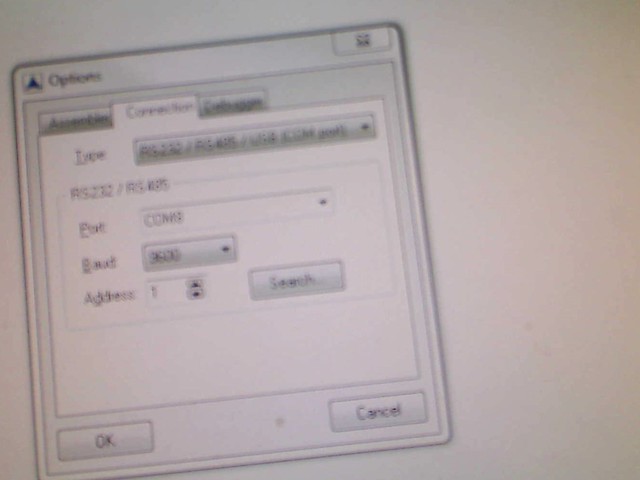
Next I start the IDE from Trinamic, links to download the software for free where presented here before and open the menu item Setup>>options which opens a small window and when clicking on the tab "Connections" it will show what can be seen in the last image and you verify that COM 8 is selected.
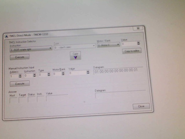
Then you click on the icon that shows a hand pointing upwards or select the menu item "TMCL>>Direct Mode..." to get the window open as shown in the picture. I have extensively introduced the functionality of this window, the GUI, before. please verify you have setup the parameters i mentioned above as shown above, the write into the text box for "Value" on the left the value of 512 and click on execute to have the stepper motor start rotating!
http://www.flickr.com/photos/hellmut1956/9132095015/When you click on the link above you will be able to see my first video in this tutorial with the stepper motor rotating slowly at a velocity set to 419 out of -2047 to +2047 possible velocity values, approximately 1/4 of the maximum velocity value, but far away from the maximum speed I can reach!


 Author
Topic: Stepper motors (Read 17529 times)
Author
Topic: Stepper motors (Read 17529 times)