Via email to Mayhem...Hello Martin and all modellers,
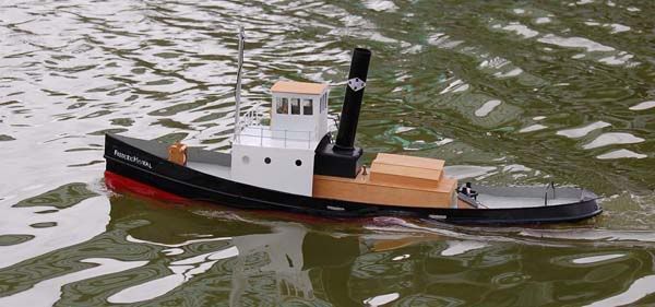
I am Geoff Probert, living in Taiwan, and trying to model the tug 'Frederic Mistral'.
I have used a small, geared, aircraft-style motor for my tug and it gets hot. Very hot indeed.
the reason for this tale
The obvious 'cure' was a cooling fan, so - like many other people - I chose a 'computer fan'. In fact I used two, one directly under the engine-room hatch, blowing down on the motor and another in the boiler casing, blowing up the funnel.
In the bathtub this seemed to work OK but in the big, wide world of the pond it simply does not blow enough air through the boat to do any real cooling so after a half-hour at pottering-about speeds, the motor is too hot to touch. Alright, I know modern motors can sustain much higher temperatures than the good-old oldies but ...
Anyway a few bystanders had suggested she would look good with smoke puffing from the stack. That started yet another distracting line of experiments, but that's another story as they say.
A promising-sounding idea I spotted (was it on Mayhem?) is heating a glass tube, rigged as capilliary, and boiling a miniscule amount of water. Voila, real steam. But this could consume oodles of power from my already hard-pressed battery/accumulator. What if I could pre-heat the water? And cool that blooming hot motor as well.
OK, I need a flow of water to cool the motor, I wonder if I can get it from the propwash, ala IC-engined how's-yer-fathers. I taped a length of aquarium airline onto the rudder, facing the prop of course, and set her going full throttle in the bathtub. Well, I got a dribble just up to deck-level. So much for that idea.
Where in this town might one get a very small water pump? Answer: One can't!
Could I build one? and would it work? And so began this little exercise: Build a centrifugal water pump as small as possible and see what it can do.
My equipment comprises a miniature metal-lathe, a scrollsaw for woodwork on the boat, and some hand-tools.
I need: a motor, a casing in two halves, an impeller and a shaft-seal.
I have: a motor and a seal from a defunct electric toothbrush ( The motor runs, drawing 150mA (about 1/8 Amp) and I reckon my batteries will stand that extra load), some 5mm brass plate, a small amount of brass bar, and a large amount of mistakes in my background. Let's try to spec it out.
The casing: about 20mm square, four screws holding the two parts together, volute (posh term for where the impeller lives) about 12 or 13mm diameter to clear a 10mm impeller. Inlet hole, as big as I can make it. No, on second thoughts, make it four millimeters, to suit the aquarium tubing I have.
The impeller: Hmm. It's just a disc with stuff cut away to leave blades. How? Dunno, think about it later....
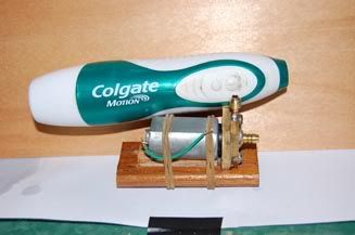
The pump The 'finished' thing (Mk I) would just about
fit back into the original toothbrush.
When do we ever declare something 'finished'?
The back is just a plate with a shallow recess to 'fit' the toothbrush' seal - about 1mm deep by 8mm dia. and a through hole about 2.5mm to clear the motor shaft. Two (M3) holes in one edge accept fixing screws from the baseplate (otherwise called 'a lump of wood.') Four M3 holes near the corners will take the screws holding the front (casing) to it.
The casing (volute) is another square of 5mm brass, with a recess 13mm dia by 4mm deep, and a through hole 6mm dia for the inlet - I'll solder the thing in. The outlet (delivery) is a 3mm hole drilled from one edge and aimed at a tangent to the main recess. Four holes 3mm clear pass the fixing screws to the backplate.
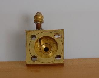
Inlet and outlet connectors are basically a bit of brass tube, big enough to be tight in the aquarium tubing, and soft-soldered into the volute casing.
The impeller, over which I spent a long time worrying, turned out to be simple. It is a disc just under 12mm dia. by 2mm thick with a slight boss for the motor shaft. By guesswork I sawed four chunks out of the disc, very gingerly on the scrollsaw (and counting my fingers frequently) so I was left with a sort of Maltese cross.
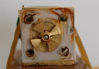
As the photo above shows, alignment was achieved by 1mm ply packing, a bit of a wedge-shaped planking offcut, elastic bands and hope!
The centre hole was supposed to be tight on the motor shaft. Oh, well, Locktite to the rescue!
By the way, the white stuff seen here is the remains of a paper gasket - plain, old photocopy paper. When I reassemble, I had better use greaseproof paper
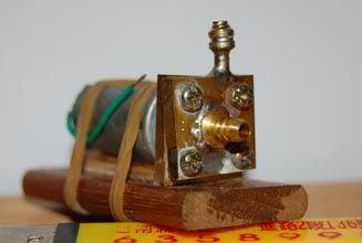
And it worked! With 6V supply it pumps water to a head of about 1 metre. I am amazed and flabergasted. Current draw ranges from 220 mA at maximum head (pinched-off the delivery tubing, so no flow) to about 235mA with a jolly good looking output.
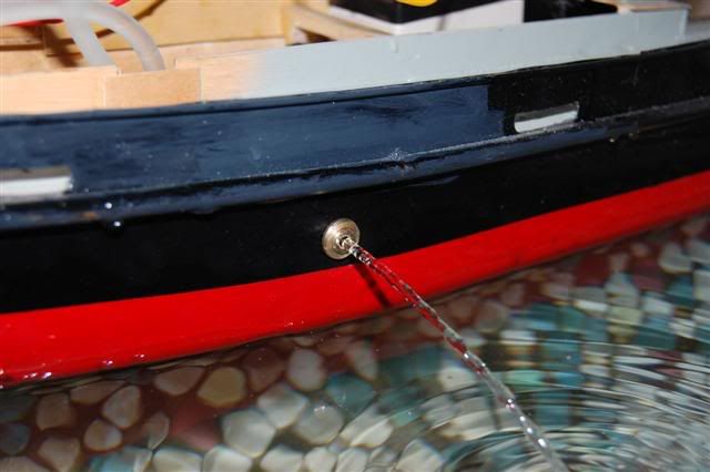
I took this photo much later, in the bath. I just hope it works as well at the lake!
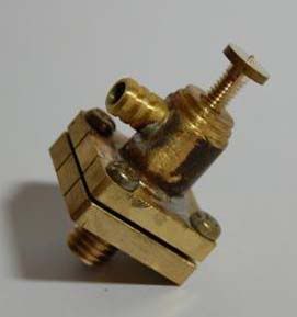
The main drawback with centrifugal pumps is that they cannot stand air in the casing. All suction is lost, nag, moan, much wailing. And when I lift my boat from the pond, the water will run back out of this amazing plumbing system. I need a check valve. I also need a seacock at the inlet. Combine the two et voila:
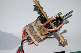
Before drilling any holes in the boat, let's test this a bit further: cooling for the motor. Just wrap some copper tubing in a spiral round the motor, right? Wrong. There's a plastic housing for some bearings tight against the motor (see second photo, above.)
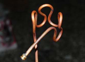
So I looped the tube back-and-forth, like this (all bright and copper-coloured after annealing):
cooling 'coils'
and it 'fits' on the motor like this.
Those massive loops are because a/ I did not want to risk kinking/flattening the tube in a tight bend and b/ it's the size of the finger that I used as a soft former.
After much testing I still could not be sure that it was carrying-off heat from the motor. Oh damnit, install it anyway - at worst there would at least be a pretty-looking discharge from the side of the boat, and the motor getting hot, like it did before!
Both holes in the hull were drilled small then opened up with a burr in the Dremel, and 'O' rings fitted on the outside of the hull. These perform the additional task of maintaining some tension on the threads of the fittings, preventing them unscrewing (fingers crossed.)
The seacock in place. Soft tubing will connect it to the pump.
By the way, in this photo you can also see the propshaft's inner bearing.
It's the wood block just south of the drive gear. It is teak and is simply a push-fit over the aluminium stern tube. It seems to be fairly forgiving to poor alignment, infrequent lubrication and side-thrust from the driving gears.
I know it is not water-tight and neither is the outboard bearing. I squeeze some Vaseline into the tube, then re-assemble the shaft, rudder etc etc. A laborious job that is not done often! And that mostly stops the dribble.
Testing, at last!In the bathtub, motor at full power, pump running, water flowing and....
The motor still gets hot!
Back to the drawing board!
It is obvious (with hindsight, wonderful stuff) that the (at best) line contact between tubing and motor-casing cannot conduct much heat. Now, if I could make a water jacket for the motor. But that blasted plastic bit gets in the way, again, so I cannot make an annulus.
I cut a piece of 5-thou brass (shim stock, all I have except the 5mm plate) and wrapped it round the motor either side of the annoying plastic, then slid the mess of copper 'coils' over it.
* keeps the copper in place;
* affords thermal conduction between copper and the brass sheet (I hope.)
And lots of silicone heat-sink compound should help to make decent contact with the motor:
Pulled tight to the motor with electrical ties:
Back to the bath...
Same test as before, motor at full power, pump running, water flowing and....
The motor is stone cold after five minutes. Eureka, maybe!
Turn off pump, leave motor running
Motor gets hot very quickly, under a minute
Pump on, motor cooling quickly.
(Marvelous things, these fingertip thermometers.)
Must try it at the pond!


 Author
Topic: Cooling a small electric motor (Read 5914 times)
Author
Topic: Cooling a small electric motor (Read 5914 times)