Hi again guys, finally found a bit of time to put on a further update.
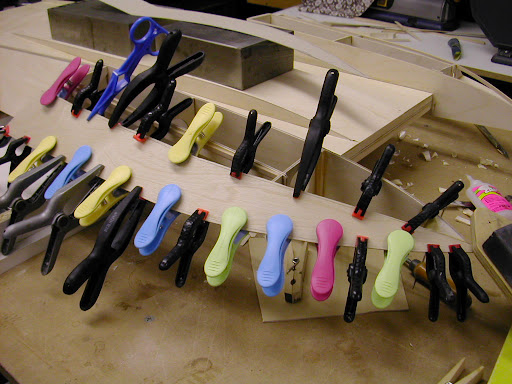
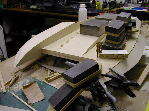
Following on the lower sponson skinning was finished off before turning it back on the jig and taking stock of the insides. Lots of clamps need for this as well as weights as you can see but it all went well. Glue used is Titebond 3 - this has been used for the entire build except the engine area. Excellent glue, very quick grab time, but not easy to sand.
Back on the jig it was time to establish the fuel tanks and radio gear. The tanks are made from SWMBO'S hair 'stuff' aerosols. Marked 200ml they actually hold 250ml each. I got the caps off using a crude cutter piercing the top in stages. I had previously tried prising it off but this left the top distorted and flimsy. A couple of ally caps were turned and fitted with brass nipples. The feed system is the R/H tank is pressure fed from the exhaust, clunk weight in R/H side feeding to the L/H tank then clunk weight pick up for the engine feed. This was based on info gleaned off the forum and the guys at the lake. My main concern was that tanks from tinplate may rust on the inside and though I have made countless tanks over the years for aircraft have never had this problem. However I have had - despite intense cleaning methods - residue of flux turn to wax like deposits that will clog the needle valve with annoying ease. Thing was those tanks were easily removed to sort the problem out and these weren't going to be hence the choice of 'drawn ally' aerosols. These 250ml were the largest I could get in the available space so how long an OPS-60 at full chat will last on half a litre remains to be seen.
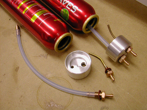
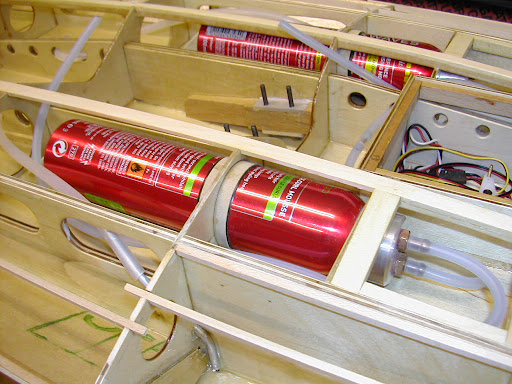
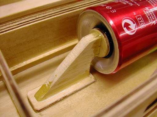
The ally caps are glued on using 'JB Weld' and the tanks are held at this point, supported in the middle by a band of insulating tape and 1/32 ply and at the rear by a button of 'silicone' May be a bit overkill but they're in there for the duration so wanted to be sure. At first the tanks were going to be totally 'buried' but I have decided to make small hatches over the front ends to access the nipples so these at least can be 'got at' for cleaning if neccessary.
The radio gear sits in front of the engine - weight in front of the C/G - with the rudder servo remote in another box aft, the servo lead running through the black tube seen on the earlier pics.
This was done as an effort to reduce the weight at the rear and to give a short and rigid pushrod to the rudder.
A little bit more then a bit later!
Mart - it is going to have transom mounted strut but with the prop close in - about 11/4" overhang. This is how the drawing is set up. However - having followed a lengthy discussion on this matter on R/C Universe provision has been made to retro mount the strut brackets inside the strut coming through the bottom skin. This would give a submerged drive with the prop position just under the transom.
I can still use the flex shaft for both - obviousy I will have to shorten it but the angles involved look very close to each other. Remember chaps I have no idea how these thoughts will pan out this side of things is my steep learning curve but I am going to enjoy myself doing it - Andy,
You can't wait to see it goooo have a guess how I feel.
Ian, I notice I made a complete boo boo

Again I think I have looked at this from an aircraft perspective - to counteract torque the side thrust is normally set to the left.
I did mean the aircraft turns left with torque - side thrust to the right - dyslexic brain again
Bye for now - Ramon
BTW I have not forsaken the Huntsman. It's just that the weather has not been suitable for spraying enabling me to make quite a bit of progress on this one


 Author
Topic: 1/8 scale hydroplane 'Atlas van Lines' build (Read 54319 times)
Author
Topic: 1/8 scale hydroplane 'Atlas van Lines' build (Read 54319 times)