Model Boat Mayhem

Please login or register.

Login with username, password and session length.
Pages: 1 2 3 4 5 6 [7] 8 9 10   Go Down

Author Topic: 3/4" to the foot model of Lowestoft Sailing Trawler Master Hand LT1203  (Read 103489 times)

Greggy1964

  • Guest
Re: 3/4" to the foot model of Lowestoft Sailing Trawler Master Hand LT1203
« Reply #150 on: February 11, 2011, 09:10:11 pm »

Have you ever wondered how that awkward plank right at the top of the stern post should go so the planks go from vertical to horizontal at the stern?


Well now you know! :-))

This of course is in the rough and I'm playing again cos it helped me get it clear in my mind too! {-)
Logged

Greggy1964

  • Guest
Re: 3/4" to the foot model of Lowestoft Sailing Trawler Master Hand LT1203
« Reply #151 on: February 11, 2011, 09:27:52 pm »

Hello Geoff,

Your too kind, thank you :-)

With regards to the curved planks thing, I'm going to use a combination of Andy's suggestion of scarfing and your suggestion of butt joins but land them at frames. I don't like butt joint straps on the back of planks so if I can't make them land on frames I'll scarf them :-))

Logged

Greggy1964

  • Guest
Re: 3/4" to the foot model of Lowestoft Sailing Trawler Master Hand LT1203
« Reply #152 on: February 12, 2011, 12:17:33 pm »

I've been pondering how I'm going to control the rudder over the last week or so and taking on board how Hammer manages it in his sailing trawler.

The problem I've got is that I'm reluctant to carve up my nice new rudder trunk of which I'm quite proud.

Last night I had a bit of a revelation as I was fiddling at 2am as I do often! %) but at the time I was chasing a totally different problem! :o

Recently I bought a drill attachment that allows me to drill around corners (see post 131 :-))) and I noticed last night  . . .  erm this morning that the chuck jaws close down to nothing.

You see I've been looking for a way to drill tiny holes in which to drive the pins I'm using to nail planks, I bought some cheapy pin vices a while back but they turned out to be as much use as a crotchet parachute {-) as drills just slip when under load.

This chuck I mentioned can hold onto a hair and tighten down on it using a chuck key. If I snap the head off of one of my hard dressmakers pins I have a makeshift tiny drill bit which is quite suitable for drilling into wood.

I've ground the diameter down from 1.65mm to 1.5 buy fitting it to the chuck and sandwiching the pin between two diamond sharpening stones and spinning the drill, thus  1.65mm pins driven in a hole bored by this new drill bit grip like hell on a lifetime sinner! O0 plus I don't bend my soft 16mm long pins while driving them in :-))

But I digress . . . . . .

The unit the chuck is part of is drives through 90 degrees to the drill axis which makes drilling for my planks awkward  . . . . .  so I took the unit to bits and of course it was driven by bevel gears!

That's IT!

I immediately dug out a note pad and began scribbling and a scan is below for your delight and delectation :-)


Ignore Em361 - I have no idea what it is, it just happended to be on the piece of paper I found on which I urgently needed to scribble - focus on the pencil drawing! :-))

The shaft angle is 60 degrees and the horizontal shaft is buried in the deadwoods with a quadrant of a bevel gear on the stern end which engages on a matching quadrant rotating on and centered on the rudder pintle.

As I only need 45 degrees either side of centre for the rudder to pivot, so I reason I only need 1/4 of a gear for each component part which can be got from one single gear of about 1" in diameter

I plan to use a brass gear so that I can silver solder brass brackets to the cut faces which will pass either side of the rudder stock and bolt through it.

This way I only need to hack out the top part of the dead woods and part of the back face of my nice new rudder trunk without ruining it and if I do it right it can all be buried under the deck maintenace free :-))

A rudder servo fitted just aft of the mizzen mast, or better still another gear shaft driven off the forward end of the horizontal shaft mentioned above and set parallel to the hull centre line will take drive to the main radio gear bay in the centre of the hull, will operate the rudder.

I'll box in the gears at the rudder so that if any water does find its way up the rudder trunk, it will get no further than the 'gear box' and drain back out through the rudder trunk.

Anyone know where I can obtain such a gear?
Logged

derekwarner

  • Full Mayhemer
  • *****
  • Offline Offline
  • Posts: 9,457
  • Location: Wollongong Australia
Re: 3/4" to the foot model of Lowestoft Sailing Trawler Master Hand LT1203
« Reply #153 on: February 12, 2011, 08:09:24 pm »

Greg....if you cannot find a small bevel gear set in an old kitchen appliance....try these people...I think their engineering plastic gear sets are not $ prohibitive .....

http://www.smallparts.com.au/store/partslist/gearsbevel24pitch/gearsandgearing/wide/1/

If these are too large in diameter try a hobby shop that specialises in RC car sets........they may have differential spares .....Derek  O0
Logged
Derek Warner

Honorary Secretary [Retired]
Illawarra Live Steamers Co-op
Australia
www.ils.org.au

Greggy1964

  • Guest
Re: 3/4" to the foot model of Lowestoft Sailing Trawler Master Hand LT1203
« Reply #154 on: February 12, 2011, 10:00:31 pm »

Great idea Derek :-))

I'd never have thought of that!

I been digging in my old stuff and I still have the differential from my long ago dead & defunct Kosyho Scorpion

Pulled the gearbox to bits, chucked the planet gears back in me bits tin . . . . .


Look what I got! And they mesh at 60 degrees too :-))

The Vintage Koshyo Scorpion Appreciation Society are going to be screaming at their monitors next! :o


I've mocked up the rudder stock to scale size, its just missing the rudder blade. :-))

The pins represent the spacing between the stern post and the forward face of the rudder where the gudgeon's and pintles will eventually go, I've cut away part of one bevel gear to straddle the rudder stock and the pintle will pass through the gear centre positively locating it.

Eventually a brass strap will be nailed and superglued to the rudder stock and gear hub locking everything in place.


Also in my scrap box I found two Tamiya Sand Scorcher gearbox gears (cringe at more screams!), these are going allow me to side step the mizzen mast with a long lazy shaft to the radio bay in the centre of the ship. At the blunt end of this shaft will be mounted a standard tiller arm that would normally live at the top of a rudder post in a more conventional boat setting O0 to which I will attach the rudder servo via a ball and socket type link arm.

I've been playing with my mock rudder stock as I've been a little concerned at the shape of the opening of the rudder trunk as it exits the bottom of the hull. {:-{


But I needn't have worried


Rudder hard over to port! O0 Skippers gone over the bulwarks hanging on to the end of the tiller! {-)

Thanks again Derek for the tip! O0


Logged

Hammer

  • Guest
Re: 3/4" to the foot model of Lowestoft Sailing Trawler Master Hand LT1203
« Reply #155 on: February 13, 2011, 05:54:14 pm »

Greggy, Brilliant,  :-)) I like it. Hammer
Logged

dreadnought72

  • Full Mayhemer
  • *****
  • Offline Offline
  • Posts: 1,892
  • Wood butcher with ten thumbs
  • Location: Airdrie, Scotland
Re: 3/4" to the foot model of Lowestoft Sailing Trawler Master Hand LT1203
« Reply #156 on: February 13, 2011, 07:36:52 pm »

Is there any slop in the differential set-up, Greg?

I'm currently wondering how to approach the steering in Racundra, given that I've a tiller on board and precious little else in terms of space to attach things to.

(That said, I'm developing a cunning plan...)

Andy
Logged
Enjoying every minute sailing W9465 Mertensia

Greggy1964

  • Guest
Re: 3/4" to the foot model of Lowestoft Sailing Trawler Master Hand LT1203
« Reply #157 on: February 13, 2011, 08:38:57 pm »

Hello Andy

I'm telling fibs! :embarrassed: The gears I'm using are from an old Tamiya Falcon and not a Koshyo Scorpion :embarrassed:

I owned both cars as a kid and that's where the confusion has crept in. Sorry!


Here is the diff complete as taken from the gearbox, I'm using both bevel gears and the rest is going back in my bits box


The two gears that I'm using to bypass the mizzen mast are spare final drive gears from a Tamiya Sand Scorcher


I confess that when I was a brat I trashed my Tamiya Falcon early on after building it. It was all plastic and could not stand up to the punishment my Sand Scorcher could take so the gearbox didn't get much mileage, I bought the car in the 80's

There is no slop that I can tell at the moment, but I've only jury rigged the setup at the mo so I won't know for sure till I get to the rudder build stage.

The falcon diff parts can be had on ebay here for £14.99 for the complete unit.

http://cgi.ebay.co.uk/Tamiya-58056-Falcon-Striker-Sonic-9335023-Gear-Bag-NIP-/380312252526?pt=UK_ToysGames_RadioControlled_JN


And the Sand Scorcher final shaft gear can be had on ebay here for £4.99

http://cgi.ebay.co.uk/Tamiya-Rough-Rider-Sand-Scorcher-Ranger-Final-Gear-NEW-/380128551901?pt=UK_ToysGames_RadioControlled_JN&hash=item58816d63dd

But if its any consolation I hate a sloppy rudder too >>:-(

 {-) O0
Logged

Greggy1964

  • Guest
Re: Master Hand LT1203 Rudder control assembly
« Reply #158 on: February 14, 2011, 01:25:10 pm »

More thoughts on rudder control and how I'm going to assemble it.

I've been studying the bevel gears I'm going to use and how the gear is going to positively locate on the end of the lazy shaft so that the torque transmitted from the servo to the shaft will be transmitted to the bevel gears and hence cause the rudder to swing. ;)

I noticed that the hole in the centre of the gear has two opposing flats so I did a bit more digging in my bits box and I found some more bones of the long dead Falcon car . . .


Here is the complete drive system for one side from gearbox to rear wheel . . . .


The half shaft fits into the gear and originally a short free rotating shaft ran through the main diff gear and into a matching hole in the opposite half shaft.


The metal shaft that the gear was originally fixed to is 4.95mm diameter with two flats cut into the end. The hole at its centre is 2mm diameter. I'm hoping I can make a brass lazy shaft to the same diameter and match the end of the half shaft. I will drill and tap the end to accept a small bolt and washer setup to hold the bevel gear firmly on its end.

The lazy shaft will either be housed propeller shaft style, but I only have 13mm width of deadwoods in which to house it at the rudder so I may just sleeve the lazy shaft in a snug fitting brass tube and solder a grease nipple at its inboard end.

This setup will bring the lazy shaft unit diameter to about 6mm which will not weaken the deadwoods unduly - I've got the think of the strain the mizzen mast heel will impose on the same area you see! :-)) O0

Right! Now that's sorted - switch brain cell back to planking mode :-)) {-)
Logged

Greggy1964

  • Guest
Re: 3/4" to the foot model of Lowestoft Sailing Trawler Master Hand LT1203
« Reply #159 on: February 16, 2011, 11:13:11 pm »

Right,

I've spent the last day or three messing around making sure that frames both sides of the hull match and are mirror images  %),

I've done this by making cardboard templates of the beveled edges of all frames (particularly at the bow and stern where the bevels are acute) and transferring them to the opposite side of the keel.

I've then sprung battens around on the port side and with my vicious sanding sticks have sanded the bevels in under the battens while checking their lay along the hull, I've gone mad and gone a little low in spots but I've been careful not to alter the frame edges taken from the plans.

Confession time . . . . .

For some reason I can't quite fathom, frame 18 (the last one forward of the stern post) - see sections below . . . .

Frame 18 wants to be more wine glassy than it already is? >>:-( {-)


The red line is traced from a cardboard template taken from the hull superimposed over the original on my screive board. When springing battens around the hull, the original profile did not seem to fit in with the rest of the frames, so I followed what the battens were telling me and ground into the frame a little altering its original shape.

But I got a much sweeter run aft as a result which goes to show it ain't over till the fat lady sings . . . . or something like that! O0

I'm not worried, as this is what would have happened on the real ship when fairing the frames once they'd been set up on the keel prior to planking.


Port side looking forward. That dogs not glued to the floor honest! And he's not stuffed either! Its his favourite spot so he can be near his daddy! {-) O0 bless him!


Looking aft.

If I've done my job properly the hull planks should lay nicely now but I expect a little more tweaking as I progress with the planks down the hull.

Next up  . . .

fitting those guard boards :-))

Logged

derekwarner

  • Full Mayhemer
  • *****
  • Offline Offline
  • Posts: 9,457
  • Location: Wollongong Australia
Re: 3/4" to the foot model of Lowestoft Sailing Trawler Master Hand LT1203
« Reply #160 on: February 17, 2011, 05:14:22 am »

Greg...I love lofting & watching/viewing others loft work....

But from today  >>:-( .....looking aft.....outboard frame 10 appears to have TOO much belly between RL42 to RL44  {:-{

When I go back to the 9th February posting...the lines suggest that the next inboard frame No 8 has TOO little belly in this same RL location......

I hope it is not a parallel-ex error on my part........but it is so easy to review the work of others with a fresh set of eyes.....

BTW.....  :o ..I don't remember reading your planned planking glue system....please confirm......I am still a big fan of permanent bronze planking pins + the chosen adhesive .... :-)) .....Derek
Logged
Derek Warner

Honorary Secretary [Retired]
Illawarra Live Steamers Co-op
Australia
www.ils.org.au

Greggy1964

  • Guest
Re: 3/4" to the foot model of Lowestoft Sailing Trawler Master Hand LT1203
« Reply #161 on: February 17, 2011, 01:38:59 pm »

Hello Derek,

Thank you for your input though I'm not sure of your references RL42 to RL44 {:-{ ?

On saying that, comparing photos from 9th Feb to Yesterdays I can see a slight dip in the plank batten at plank 3 position (counting from the keel) on frame 8 in yesterdays photo looking aft.

In 9th Feb post, photo 5 does indeed show that a little could be shaved off frame 8 at plank batten 3 but if I remember correctly I did remedy that while comparing port and starboard.

What I intend to do as planking progresses, is to tweak things a little, it's easier to see smaller unfairness-es to my mind (and eye) when laying planks one against its neighbour.

The idea with the battens is to pick out any glaring errors in unfairness - point in case - frame 18 in yesterdays post.

I originally cut both sides of each frame from the same half pattern (taken off my carefully prepared lines plan) and cut carefully down to the line I'd drawn on the plywood.

I've also been very careful in setting up the keel and frames on the building board so technically the frames should not be too far out.

I do have a secret weapon to help me though that I haven't revealed yet . . . .


Its a 300mm long profile gauge made by Vitrex, the maximum travel of each needle is 43mm


Which can copy accurately complex profiles and I can compare port and starboard frames using it.


I plan to use this tool locally on the hull surface as I go checking side for side.

With regards to the planking process, I haven't got that far yet :-)

But since you raised the point, I plan on using Cascamite or as it has been re branded Polymite (same stuff different name!) for gluing the planks to the hull.

For nailing the planks to the hull I am using 16mm long mild steel dressmakers pins, these are primarily for holding the planks in place while the glue sets, but I will be leaving them in place driven slightly below the plank surface.


Realistically Master Hand will spend more time on her cradle than on the water so using steel pins which are readily available at my local dressmakers shop won't be a problem.

Its a personal choice and one I've used in the past on my models with success :-))

I plan to coat the exterior and interior of the hull in either polyester resin or SP systems Spacoat 320 epoxy resin as my budget allows at that time and depending on upcoming experiments.


You see I want the plank seams to show on the finished model which is why I'm going to great lengths to plank to scale. The original ship was built to a high standard - for a working boat, but she would not have had a glass smooth hull and I want to try and emulate this in the model.

The only problem with SP 320 epoxy resin is that it will make the whole job look lovely, highlighting the grain in the oak planking so well that I won't want to cover it up with paint! O0 {-)

I plan to give photo by photo details of the whole planking process as I go, with all hiccups, challenges and successes so that folks can see that they too could plank a hull to a good standard given time and effort :-)

Logged

Greggy1964

  • Guest
Re: 3/4" to the foot model of Lowestoft Sailing Trawler Master Hand LT1203
« Reply #162 on: February 17, 2011, 02:22:42 pm »

 >>:-( Erratum! <*<

Line 4, post 161

Quote
In 9th Feb post, photo 5 does indeed show that a little could be shaved off frame 8 at plank batten 3 but if I remember correctly I did remedy that while comparing port and starboard.

should read

In 9th Feb post, photo 5 does indeed show that a little could be shaved off frame 10 at plank batten 3 but if I remember correctly I did remedy that while comparing port and starboard.

 :-))
Logged

Greggy1964

  • Guest
Re: 3/4" Sailing Trawler Master Hand - the best laid plans of mice and men!
« Reply #163 on: February 18, 2011, 06:31:45 pm »

We I've come to the point where I lay the first planks and being a part time perfectionist I've come across a tiny hiccup :o

My house is heated by a warm air central heating system which makes the atmosphere very dry and it plays havoc with wood! <:(

And Ive discovered a tiny bow in the length of Master Hand's keel near the bow >>:-( >>:-( >>:-( >>:-(

Now were not talking banana style bent . . . . it's like in the order of 0.65mm

Imagine a 900mm spirit level forming a chord of a circle and the keel forms the arch subtended by the chord and the 0.65mm being the maximum tangent . . . .

That's what we're looking at here so its tiny but its driving me nuts. >>:-(

Nothing else has moved, I have cotton string lines stretched down both sides of the building board and its surface is level in both planes and the keel is still flat on its sole.

It's just bent slightly port to starboard near the bow.

So I've come up with a plan.

The grand scheme is to clamp my trusty spirit level to the side of the keel as I lay the first few planks either side forming a stiff 'T' in section.

By the 2nd or 3rd plank laid per side, this should be enough to hold things permanently straight and I can take away the level. :-))

Using my bench grinder I've modified 4 cheapy 3" G clamps to allow me to clamp to the keel side cut leave clearance to lay the planks


Which I'm using to clamp the spirit level to the side of the keel. O0


I can fit the guard board to rabbet in the side of the the keel without interference %)


Just one more hiccup *sigh!*  {-)
Logged

nemesis

  • Full Mayhemer
  • *****
  • Offline Offline
  • Posts: 1,070
  • Location: North Shields. Northumberland
Re: 3/4" to the foot model of Lowestoft Sailing Trawler Master Hand LT1203
« Reply #164 on: February 18, 2011, 08:06:00 pm »

Hello, Read your comments on your problem with steering, could you not use an endless loop system, could end up being more simple.
                                                           Nemesis
Logged

Greggy1964

  • Guest
Re: 3/4" to the foot model of Lowestoft Sailing Trawler Master Hand LT1203
« Reply #165 on: February 18, 2011, 10:08:23 pm »

Hello Nemesis,

Yes I has considered the continuous loop method but I have the materials to hand for the gear system and I like something that a bit more robust O0

This ship is going to be very heavy and a bit of a beast and I want rudder controls that are man enough for the job :D but I appreciate your suggestion :-))
Logged

Greggy1964

  • Guest
Re: Sailing Trawler Master Hand planking experiment 1
« Reply #166 on: February 18, 2011, 10:42:23 pm »

Here is an attempt at laying a guard board, no glue - just nails to see how I got on.

I'm trying to highlight any obstacles cos it might get messy when using glue as well :o O0

I'm drilling through the plank and into the frames using a longer pin as a drill bit  :-))

Issues I've spotted so far are that I need a decent punch and my hammering technique needs a little work as I'm rusty in that department! {-) O0

If you don't hit these pins I'm using axially spot on they bend and once that happens they have to be pulled and binned! >>:-(


The plank I'm using was rejected as suitable for the hull but it makes a useful test piece.

I need a punch that has a fine tip but is concave to hold the pin head preventing it slipping, also I need to be able to drive the pin below the surface of the plank without bruising the surrounding area if possible. Maybe I need two separate punches for each task? Hmmmm . . . . .


The plank went on cold (no steaming as I haven't built my steam plant as yet %)) with little problem though as you can see it has split slightly at the hood ends. This will be avoided with a steamed plank as it was caused by the stress of twisting it into place.

But all in all I'm satisfied. The pins are easily man enough to hold the plank in place and I've learned a few things in the process.

Now I'll go away and degest the experience and thunk up ways of solving the issues I've come across :-) :-))
Logged

Greggy1964

  • Guest
Re: 3/4" to the foot model of Lowestoft Sailing Trawler Master Hand LT1203
« Reply #167 on: February 20, 2011, 07:05:22 pm »

Okay I've dug out the planks I cut last year for Master Hand . . .

But there's a slight snag >>:-( >>:-(

Most of the hull planks at 1/16th scale are 3.9mm thick (the full size planks were 2 1/2" thick) with the exception of the bilge strakes and sheer strakes which are 3" thick (4.8mm on the model)

I cut the planks roughly at 5.5mm thick and 6.5mm thick respectively on my circular saw when converting the old oak table, now I have to plane them to correct thickness . . . .

 :o But how to do it?  :o

I have a power planer which I dabbled with last year (see post 28 here) but it is very noisy and extremely dusty even when attached to my trusty Dyson.

No . . . .

I wanted a more genteel way with no noise and no fuss, :-)) O0 I have a number of hand planes made by Record and Stanley but my favourite for most general jobs is a Stanley with an 8" long sole.  On studying this plane it can be seen that the blade protrudes through the sole but there is a shoulder either side caused by the sides of the plane body hmmmmmm . . . . can I take advantage of this?

The answer is yes! :-))

I came up with an absolute doosey! O0 :-))

I've had some perspex strips cut 25mm x 5mm thick for years left over from when I used to work for an industrial sign manufacturing company, the strips were originally to make up laminated sail battens for my class 5 landyacht but they serve another purpose here :}

Allow me to introduce the A.C.M.E. plank planing track (patent pending)


The plane sole rides on the first shoulders which are 4.2mm thick and are set exactly the width of the plane blade apart  . . . . using the blade actually  O0. . . .


To ensure the plane follows the track and the blade travels down the plank trough a 2nd set of shoulders were set using the plane body with the blade set very deep.


And a small perspex block set at the width of the plane blade was temporarily superglued at the back end of the plane.


The plane body is guided by the 2nd tier of shoulders and in cross section the plank track gives a sort of amphitheatre effect {-) O0


The 4.2mm thickness of the first shoulders allows the plane blade to shave off the surface of a plank blank but only to a set depth and a maximum of 4.2mm.

When there are no more shavings comming off you've got down to the desired thickness :-)) ;)

Over thick planks blanks are placed in the bottom trough and clamped with the device's  open end to the workbench . . .


I can cut plank thicknesses with faces exactly parrelell and the same thickness the entire length of the plank and I can cut plank thicknesses from 4.2mm to about 1.5mm thick if required (4.0mm the desired thickness shown by the vernier calipers)

To plane thicker planks i.e. the 4.8mm sheer strakes and bilge starkes I will simply super glue two parallel strips of 1mm birch ply to the sides of the sole of my plane either side of the blade and adjust the blade to suit O0 :-)

I've gone through 1 and a half bottles of runny superglue to make the track but it's worth it   . . . . .

 :-)) cos the thing works like a charm  :-))

And the good thing about perspex is  . . . that when it's glued with super glue it stays glued :D

Next job . . . . .

Build me a plank steamer doobly :-))  ;)
Logged

derekwarner

  • Full Mayhemer
  • *****
  • Offline Offline
  • Posts: 9,457
  • Location: Wollongong Australia
Re: 3/4" to the foot model of Lowestoft Sailing Trawler Master Hand LT1203
« Reply #168 on: February 20, 2011, 07:20:28 pm »

Necessity being the mother of invention Greg....you have devised an excellent solution.... :-)) ....Derek
Logged
Derek Warner

Honorary Secretary [Retired]
Illawarra Live Steamers Co-op
Australia
www.ils.org.au

Greggy1964

  • Guest
Re: 3/4" to the foot model of Lowestoft Sailing Trawler Master Hand LT1203
« Reply #169 on: February 20, 2011, 11:51:58 pm »

 :-)) A copy of  :-))

Sailing Trawlers: Story of Deep-Sea Fishisng

by E.J. March published by David & Charles, 1981, 3rd impression


has been listed on Ebay

just in case anyone is entertaining following in my footsteps  ;)

http://cgi.ebay.co.uk/ws/eBayISAPI.dll?ViewItem&item=380318389806&ssPageName=ADME:B:SS:GB:1123

It's a rare book these days  O0
Logged

Greggy1964

  • Guest
Re: 3/4" to the foot model of Lowestoft Sailing Trawler Master Hand LT1203
« Reply #170 on: February 21, 2011, 04:12:42 pm »

So you been with me so far and you've done each step right?

All that work and seemingly getting nowhere making the keel and cutting the rabbet for the guard board O0. and the bevelling all those frames  :o

Well now all that work will start to pay dividends  O0

Now its time to lay those first two planks :-))

Start by making a template from cardboard of the hood end at the bow . . . .


Make it as accurate as you can, I cut the rabbet to accept a square edged plank (review posts 27 onwards) to make things a bit simpler when laying the guard boards and subsequent planks :}

In full size practice the rabbet would have been cut shallower and they'd have shaped the mating face on the plank to fit. This was to avoid cutting too deeply into the keel's side face thus weakening it.


But since we're not relying solely on tree nails and bits of string caulking to hold on the plank and keep the water out, but we're bonding the guard board as well as pinning it in place . . . .

we can get away with our method ;)


My planking stock width is dictated by the thickness of the table top from which they were cut (21mm) so I've made my template the same width to ensure I have no alignment problems, I've also indicated where frame No.1 is on its face. We now transfer all this info to our chosen plank stock.


Mark the plank with a sharp pencil and transfer frame No.1 position also and cut away the waste.

Remember! We sand away until the pencil line just disappears to match the template, sounds obvious I know but the pencil lead is up against the template edge and the pencil line has thickness no matter how sharp! %)

Offer the plank up to the keel and try for fit, and using our nasty sharp sanding sticks (see post 138) whittle away at the shape of the hood end until you get a perfact fit.


Keep whittling, trying for fit, whittling, trying for fit, etc. until you're happy. Don't go hacking away and end up starting again further down the plank . . . .  we don't want to get into the Laurel & Hardy sawing the leg off a wobbly table syndrome :o {-)

All the planking stock I have is not long enough to make even the shortest plank on the hull in one piece  >>:-( so I'm making the guard board joint a butt one at frame frame 12.

You will have noticed I've pinned the plank in place and I've pre drilled for all the pins I will be using when fitting the plank permanently, this is a time saving exercise because at that time the plank will be slippy with glue  :o and we want to make our lives at this sticky time as simple as possible. So make tick marks on the keel and plank at various points to help alignment so you find these holes in the keel and pins will just fall into place :-))


I've clamped my spirit level to the other side of the keel to help take the shock from hammering in all these pins so the whole frame takes the load and not just the keel at the bow :-))

It goes without saying that you do the same procedures to the other side of the keel okay? O0

Next time . . . . .

Making the tail end of the guard board . . . .  :-)

Logged

Greggy1964

  • Guest
Re: 3/4" to the foot model of Lowestoft Sailing Trawler Master Hand LT1203
« Reply #171 on: February 21, 2011, 07:06:36 pm »

Right, now for the tail end of the guard board . . .

As before, make a cardboard template as accurate as you can and transfer this to the plank blank and cut out making the butt join slightly longer . . .


Sand carefully and then pin and clamp as necessary the hood end at the stern post.


Twist the plank so that it's bottom edge fits into the rabbet and offer up the butt end to its mating face on the forward part of the plank . . .


Carefully sand way at the butt and try fit - sand, try fit - sand, try fit - sand, etc. etc. . . . .


I found clamping a small scrap of wood between the keel and plank helped hold it steady while I worked . . . .

Remembering all the time the 'wobbly table leg syndrome' as a constant reminder to go careful %)


A good tip when you're getting close is to under cut the face slightly and you will find you can see the back face of the plank beginning to fit the seam . . .

At this stage square up the front face of the butt and the plank will slip neatly into place  :-))


Here is a butt ugly (scuse pun) closeup of the finished seam . . . .  those pin heads look a mile wide don't they?

In reality they are only 1.65mm in diameter!  :o

While the plank is in place we might as well set out it's top edge . .


In an earlier post we set out the widths of the guard boards and a number of others for the plank runs, and from this we know the guard board is 15mm wide, I set this out on the plank in situ using my trusty vernier calipers (this tool gets abused but I use it for jobs like this all the time).


A straight edged batten is strung around the little dents made by the calipers and the top edge of the plank marked in pencil . . .


The batten is removed and the new plank edge thus set out is checked for any wobbles . . . . .


And any found are corrected  :-))


All that is required now is to take off both parts of the plank and place them in our A.C.M.E. plank clamp and plane down to the new plank edge.

The resultant plank can of course be used as a pattern for it's oppo on the other side of the keel O0

Its important to get a nice sweep to this new edge because the 2nd plank takes it's bottom edge from this  . . . . . so nice sweet sweeps please  O0 . . . . no dog legs or kinks

 <*< If you don't mind!  <*<

 {-)

The rest of the planks are made in a similar fashion with a few variations . . . . .

 :o  Only another 41 to go!  :o

 %) {-)

Logged

Greggy1964

  • Guest
Re: 3/4" to the foot model of Lowestoft Sailing Trawler Master Hand LT1203
« Reply #172 on: March 02, 2011, 12:06:59 am »

Just thought I'd give you an update . . . . .  :-))

I'm running planking stock through the A.C.M.E. plank track . . . .


Just doing the grid . . . .

And I've a lot to go through.

Starting off taking the thick stuff off . . .


and working down the the thin stuff . . . .


And I mean really thin!  :o


My planks are comming out between 4.1mm and 4.3mm thick which is good because it gives me room to scrape the finished hull smooth down to the desired 4mm :-))

And I'm filling my kitchen sink with shavings ejected off the end of me plank track, I'm saving those for later %)


Some planks are straight . . . .


Well reasonably!  {-)

And . . . .


While others are obligingly curved . . . . . great for those curvy planks we discussed in an earlier post!

Funny really because all planks came from the same flat oak table top  :o O0

I'll be sorting the curved ones special for those awkward curvy bilge planks  O0

And no . . . . . .


Simba still hasn't moved!  :o  . . .  . . . but he really is alive . . .honest! :o

 {-) {-)

And just to prove it . . . here he is accompanied by his feline friends . . .


The reason for his expression is that I couldn't get him to sit still and pose would you believe! >:-o

So I had to bribe him with a cube of Kite-Kat cat food held in my left hand which is what he's ogling at!  {-)

And is also the reason for him being mobbed by cats!  O0 {-)
Logged

dreadnought72

  • Full Mayhemer
  • *****
  • Offline Offline
  • Posts: 1,892
  • Wood butcher with ten thumbs
  • Location: Airdrie, Scotland
Re: 3/4" to the foot model of Lowestoft Sailing Trawler Master Hand LT1203
« Reply #173 on: March 02, 2011, 03:46:14 pm »

Couple of questions, if I may?

1/ How long does an individual plank take to shape from blank stock and fit?
2/ Do you cut the other side's planks at the same time as the working side's?
3/ Does the other side's plank need any fettling (i.e. are you sure the hull's 100% symmetrical)?
4/ Real boats made this way would be caulked for watertightness. Would it be possible (or desirable!) to achieve this at this scale?

Andy
Logged
Enjoying every minute sailing W9465 Mertensia

Greggy1964

  • Guest
Re: 3/4" to the foot model of Lowestoft Sailing Trawler Master Hand LT1203
« Reply #174 on: March 02, 2011, 07:26:14 pm »

Hi Andy,

Time taken from starting with a blank plank in the rough to the finished plank on the hull is difficult to gauge at the moment as I've only cut and dry fitted the guard boards which I've yet to permanently fit in place but it took about 2 hours of messing about getting the first one to fit and then using it as a pattern for its opposite took about 20 minutes.

But once I get a routine going I'm looking at about 4 hours per pair of planks from rough plank to glued and pinned to the hull. :-)) but its a guesstimate at the mo  O0

Planing a plank in the plank track, thats less of a guess, the shoulder the plane run on are set at 4.3mm off the base (not 4.2mm in post #167 [typo]). I'm aiming at a finished planed plank thickness of about 4.2mm to give me room to scrape and sand the finished hull to 4mm plank thickness.

The procedure is to set the plane fine and take enough off one side to remove tool marks left by the circular saw. This will be the inside of the plank (but this may change), the plank is flipped over and again planed to get rid of tool marks and then I'll inspect both faces and choose which will be the outside face of finished plank.

I'm looking for tearout and other defects which won't matter too much on the inside of the hull as I plan to seal it with fibre glass resin or maybe epoxy at a later date. A complete plank is formed from 1 1/2 plank blanks (three total for a pair of planks). I then plane the best side down to 4.2mm.

One plank blank takes about 5 minutes to plane up to 4.2mm which then goes on the pile to be sorted. Planks near the keel and the sheer are fairly straight while those on the bilge are curved and lazy 'S' shapes. In other words enough material to form one pair of planks takes 15 minutes or so.

Incidentally doing more research, planks were cuts straight it seems and then edge set to get them to fit the frames after steaming them to death in a steam box on the original ship so I'm going to try the same with my hull  :-))

I've taken some time to try and get both sides of the hull and frames symmetrical so that I can cut one plank and fit it to one side and in theory this can be flipped and it will fit the same spot on the other side of the hull. I'll then use this as a pattern to cut the 2nd of the pair. Obviously this is the real world and there are small differences but if they are way out I go back and investigate why and correct the issue.

I cut the 2nd plank a tad wide of the marks to allow for fettling while fitting.

This is why in the beginning I went to great lengths to set out the building board and cut each frame from one half pattern to ensure symmetry as much as possible.

My aim when fitting planks is to fit their seams closely, I do this by using something like blackboard chalk the coat the edge of the last laid plank, then by offering up it's new neighbour, chalk will be transferred highlighting high spots.


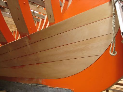
The effect I'm aiming at while planking will look like this.


And this :-)) It will take an hour or two to get one plank to fit this close but it looks beautiful when done and worth the effort in my book  :-))

The inside seam of adjoining planks will be a close fit and the outside will show the caulking groove. I'm currently pondering on the best way to tackle creating this bevel on the plank edge but I've spotted these micro hand planes on e-bay which might just do the job


It is 3" long and 3/4" wide  :o

The bevel will extend to half the plank thickness and its open face is determined by 1/16" of gap for every 1" of plank thickness so on the real ship this would have been 2 1/2 x 1/16 = 5/32" converting to 1/16th scale is and into metric money is 0.25mm which happens to be the width of a junior hacksaw blade.

What I intend to do is roughly cut the bevel on the new plank edge and when it is fitted in place next to it's fixed neighbour run a device (of shape yet to be determined) made from said junior hacksaw blade along the seam to even it up along the length of the planks.

That 0.25mm plank seam will (hopefully) fill up nicely with the paint system I intend to use on the outside of the hull leaving an impression of nice even caulked seams.


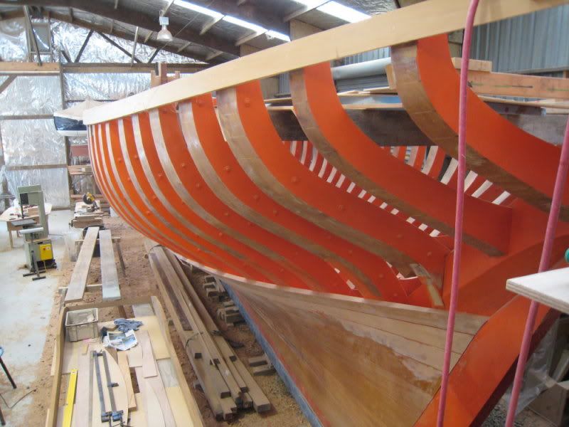
As I'm using oak for planks which is classed a durable I intend to give the outside of the hull a couple of coats of thinned varnish plus a coat or two of eggshell finish black paint to represent the tar coating used on the original ship plus the underwater areas will be painted with a reddy orange paint to represent the red lead antifouling used on the original ship.

Again this will depend on how much the plank seams are filled up with the paint finish - I want the plank seams showing so the eventual finish will be governed by this. I'm not looking for a glass smooth finish  <*<

I don't think it wise (for my sanity's sake) to try and caulk seams this small but I dare say it is feasible. You have to draw the line somewhere between a miniature built ship that is going to spend its life in a glass case, and a well presented scale model you intend to throw on the water and sail from the pond side.   :-))

I'm aiming for the latter ok2
Logged
Pages: 1 2 3 4 5 6 [7] 8 9 10   Go Up
 

Page created in 0.171 seconds with 21 queries.