Sorry for responding so late. Health continues to be a major issue for me!
Here you find my tutorial about stepper motors that should serve as a source for information and I am more then just willing to respond to any question.
There are a few things that make the difference between stepper motors and dc motors:
Stepper motors do steps and the speed is defined by how many steps per second the stepper motor can do! DC motors you use the rpm to define its speed.
Keeping in mind the just written information:
Stepper motors have their strongest torque when holding their position and the available torque gets lower the faster its makes steps. Following from this stepper motors are good when rotation speed is relatively low!
Stepper with lower nominal voltage are better than those with higher voltage when they have the same torque capabilities.
Control of stepper motors love high voltage. They require circuitry to limit the current to the maximum value defined for the motor.
Just to give you an example when I started to investigate the operation of stepper motors. I used a board with the famous L297 and L298 electronic components and fed the stepper with 12 VDC. It did never work! I found later using the "steprocker" board from Trinamic that my stepper motor would never work with that voltage when only so called full steps or a minimum value of microsteps. The stepper motor worked perfectly with that voltage when I set more microsteps.
Now to the question about a way to have a simple path to use stepper motors and control the via your RC system. RC receiver generate for each of its channels a signal that is called PWM, or pulse with modulation:
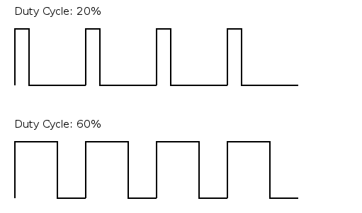
Servos require a frequency of 50 Hz or a cycle length of 20 ms. This means one cycle is 20 ms long. In this picture you see the image of 4 cycles or a time length of 80 ms! 50 times 20 ms gives you 1 second or 1 Hz!
The picture helps to explain the term "Duty Cycle". As you can see on the graph for 20% duty cycle it means that during 20% of the 20 ms of 1 cycle the signal has a voltage level of i.e. 5 VDC or 4 ms! In the graph below the duty cycle is 60% or 12 ms out of the total 20 ms and this is repeated 50 times per second! So when you pull the stick of you RC transmitter to its lower limit the PWM might have a length of 5% and when you push it to its upper limit 90% duty cycle. A servo electronic defines to which position it has to go by influence of the PWM duty cycle! The number of meaningful positions you can put the sticks of you RC transmitter is relatively limited and depending on your skill level controlling your RC transmitter. Lets assume you can set 50 different positions of the control stick.
Traditionally the circuit in the servo was made using analog technology which basically means it averages the voltage level the PWM gives to a value between 0 VDC for full pull or 0% duty cycle and 5 VDC for 100% duty cycle. Digital servos already do themselves what you have to accomplish by the use of electronics in any case! You use a "clock" a functionality within a microcontroller that "ticks". A controller that operates at 1 MHz, ticks 1024 * 1024 times a second. If you take the analogy from your PC specs it will operate at lets say 1 GHz. A clock operating at 1 GHz ticks 1024 * 1024 * 1024 times per second.
So what the digital electronic that operates with a traditional RC receiver is that it starts the a counter at the rising edge of the PWM. That is the moment in time the 20 ms cycle begins, see the vertical line in the lower graph. When it detects the falling edge it stops the counter. It compares the value of the counter with the value stored in a variable that gives the value of a counter that clicks of the full 20 ms. This way it determines the duty cycle of the PWM in the signal line of your receiver channel.
Now, comparable with the result of the analog circuit servo determines the angle position of the server arm!
A stepper motor does steps. The step position when I fully pull the stick of my RC transmitter is position "0" and the step position when I full push the stick of my transmitter forward is the position i.e. 1000. To be precise 999 as the first position is "0" and not "1"! So when my computed duty cycle length is 20 % my stepper motor has to move to the step position "200"! There are numerous example in the internet how a cheap Arduino board can be programmed to do this for all channels of a RC receiver.
Knowing that my stepper motor has to move to the position "200" is what a stepper controller has to be told to do. Just to reinforce. The position of a stick in a RC transmitter is usually in its center position. This would be applied to our example the position "500" or 50% duty cycle!
A final advice! operating a stepper motor at its nominal voltage level will usually result in very poor torque and very low speeds if it moves at all! I see many examples in the Internet where servos are operated that have i.e. a nominal voltage of 12 VDC with 12 VDC. The result is that the stepper motor either does not step at all or it has such a bad torque that as soon as it has to rotate a load stops stepping! In my sail boat where I use a stepper motor as winch is has a nominal voltage of around 2.5 VDC and I do operate it with a battery pack of 12 LiFePO4 batteries connected in series resulting in voltage between around 40 VDC, battery pack full and 24 VDC, battery pack empty! So I am using voltage level between 10 times and 16 times above the nominal value. The stepper motor controller ensures that never more than the allowed 3 A are flowing through the stepper motor coils! By the way the controller circuit does this by supplying the voltage to the stepper motor using a PWM circuitry to ensure that not more than the 3 A flow to the stepper motor.


 Author
Topic: Carina sailboat - my scratch build! (Read 18891 times)
Author
Topic: Carina sailboat - my scratch build! (Read 18891 times)