Model Boat Mayhem

Please login or register.

Login with username, password and session length.
Pages: [1]   Go Down

Author Topic: STEPPER MOTOR - very accurate position info using non contact sensor  (Read 2653 times)

C-3PO

  • Full Mayhemer
  • *****
  • Offline Offline
  • Posts: 1,107
  • I thought that hairy beast would be the end of me
  • Location: Outer Rim world of Tatooine

 I have been playing with stepper motors for a while and believe they have lots of uses in radio control models.
 
They are super smooth and via a controller board (software) you can vary the speed, step from a known position to another very accurately.
 
The biggest frustration is they have no "position feedback" unlike a servo which has an integral potentiometer which enables position tracking & fairly accurate position reproduction.
 
Often when using steppers you need to identify a "home" position when you power on and from that point you can control the position accurately by counting steps, but if you experience a power failure the position information is lost and the system needs to be reinitialised - this can lead to a non viable/complex/frustrating solution.
 
I have recently been using a non contact sensor - you simply locate the sensor near the end of shaft & position a Diametrically Magnetised magnet on the end of the shaft.
 
The sensor is accurate to at least 1/10th of a degree - possibly more - the manufacturer suggests accurate to 4 decimal places, the sensor has low latency as it can keep track of the position even at an rpm of 100,000
 
In the event of a power failure as soon as the power is restored you simply read the sensor and have stepper position information
 
If you want any more information PM me

C-3PO
 
Logged
I think it's the way I have learnt most of my stuff - getting very stuck first...

grendel

  • Full Mayhemer
  • *****
  • Offline Offline
  • Posts: 1,949
  • Location: Canterbury, Kent, UK
Re: STEPPER MOTOR - very accurate position info using non contact sensor
« Reply #1 on: November 01, 2019, 03:02:15 pm »

the very accurate motors on telescope tracking mounts use an optical sensor to count the steps and measure the angular position
Logged

C-3PO

  • Full Mayhemer
  • *****
  • Offline Offline
  • Posts: 1,107
  • I thought that hairy beast would be the end of me
  • Location: Outer Rim world of Tatooine
Re: STEPPER MOTOR - very accurate position info using non contact sensor
« Reply #2 on: November 01, 2019, 03:19:26 pm »

Hi Grendal,

Interesting - I did not know that - I wonder what the optical sensor added to the party apart from perhaps allowing a "home" position to be identified.

Correct me if I am wrong - each time you power up you still have to initialise the system (give it a start-up home position), align it to a star etc so the PID knows the state of play even with GPS enabled scopes

I was the proud owner of this for many years - had some great fun - not sure I could lift it now!!


C-3PO
Logged
I think it's the way I have learnt most of my stuff - getting very stuck first...

grendel

  • Full Mayhemer
  • *****
  • Offline Offline
  • Posts: 1,949
  • Location: Canterbury, Kent, UK
Re: STEPPER MOTOR - very accurate position info using non contact sensor
« Reply #3 on: November 01, 2019, 03:42:49 pm »

yes you pretty well have it, not many systems can remember the home position, but more now can be put into a power down sleep mode.
Logged

Hellmut1956

  • Full Mayhemer
  • *****
  • Offline Offline
  • Posts: 154
  • Best Hobby in the World!
  • Location: Mammendorf, Germany (near Munich)
Re: STEPPER MOTOR - very accurate position info using non contact sensor
« Reply #4 on: February 07, 2020, 09:20:31 am »

I have been working for a pretty long time on a system that uses a stepper motor as a winch and does monitor the actual position using an AMS magnetic angular sensor with 14 bits of resolution over each 360° giving the monitored data as a PWM signal and 12 bits resolution delivering the data following the quadrature encoder method.


https://ams.com/as5047u
https://ams.com/as5172


The great benefit of using the Quadrature Encoder I/F is that many ARM based microcontrollers have a quadrature encoder peripheral build in. Here the Link to the datasheet of the LPC1769 as an example:


https://www.nxp.com/docs/en/data-sheet/LPC1769_68_67_66_65_64_63.pdf


Here the link to a very inexpensive board from "Embedded Artists" I use. The board is so cheap, and Embedded Artists have a huge selection of so called "LPCXpresso", and so small, that making your own board is more expensive. And the board has also huge benefits. One is that it comes with a board that contains the hard and software to program and debug programs on the board using the free LPCXPRESSO IDE that includes the software to configure to the LPCXPRESSO board you choose to use CMSIC API software for all the peripherals on board.


The need for a home position is fully served by using the "Index-Signal" from the quadrature encoder I/F. I am sure C-3PO knows this, but for the rest of us a short presentation of the quadrature encoder and the use of the magnetic angular encoder:


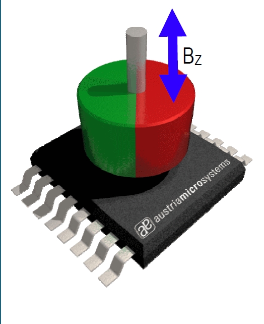
One benefits for my application in a sailboat model is that I do place the AMS sensor below the deck os it cannot get in touch with water and place a plastic cover over an opening on the deck. The magnet is connected to an axis that turns with the sail boom. This way I can have the actual position of the boom monitored with 12 bit resolution using the quadrature encoder and the 14 bit absolute resolution supplied as PWM by the sensor for fine tuning length of the sheet of the corresponding boom. The stepper motor used as winch is also monitored using an angular magnetic sensor to supply the sheet length required in accordance to the angular position of the boom!


This graphic shows how the quadrature encoder works and remember, it works with 12 bit resolution per 360° turn. Also, the CMSIC API and the quadrature encoder peripheral of the LPC1769 controller do the processing of the quadrature encoding! So you do not have to bother about low level programming. The "I" Index signal would be assigned to the "Home position" as it is issued once per 360° turn.
Logged
Best regards Hellmut
Pages: [1]   Go Up
 

Page created in 0.099 seconds with 22 queries.