Model Boat Mayhem

Please login or register.

Login with username, password and session length.
Pages: 1 [2] 3   Go Down

Author Topic: Gasoline powered Tugboat  (Read 5098 times)

Subculture

  • Full Mayhemer
  • *****
  • Offline Offline
  • Posts: 4,189
  • Location: North London
    • Dive-in to Model submarines
Re: Question about propellers.
« Reply #25 on: December 16, 2023, 03:33:50 pm »

You said this was for a tugboat, so a displacement hull and generally quite a chunky one at that.

For a scale subject, the size and style of prop is often dictated to by the original boat. We can tinker a little with the pitch and sometimes the blade shape is tweaked a bit, but overall remains a faithful miniature version of the 1:1 item.

I tend to look at what would be my desired speed and work back from that.
Logged

1967Brutus

  • Full Mayhemer
  • *****
  • Offline Offline
  • Posts: 230
  • I am in it for the learning!
  • Location: The Netherlands, Friesland to be more exact
Re: Question about propellers.
« Reply #26 on: December 16, 2023, 04:01:18 pm »

You said this was for a tugboat, so a displacement hull and generally quite a chunky one at that.

For a scale subject, the size and style of prop is often dictated to by the original boat. We can tinker a little with the pitch and sometimes the blade shape is tweaked a bit, but overall remains a faithful miniature version of the 1:1 item.

I tend to look at what would be my desired speed and work back from that.

I would tend to 100% agree... the thing is, I do not have a boat yet, and no idea what kind of boat would sport a 105 mm prop.

On another note: So far, I have assumed to be using a 15 cc single cylinder engine, and assumed that I would expect to get about 80 to 100 W out of that...

Stupid me... This thing is allready lying jobless somewhere around the home for about 2 years or so...


I still have quite a bit to modify on it, but it already HAS water cooling, a built on water pump, a built on starter and the flywheel is better suited to hook up to a drive system. I only would wish the flywheel would be a bit heavier...
But it should have no issues delivering 100 W whatsoever.

Imagine the run a bit more stabilized and regular, and the sound a bit more muffled...

How cool would THAT be?
 
Logged
If you do without observing, you won't learn a thing.
If you observe without doing, you'll never know if what you learned was true.

1967Brutus

  • Full Mayhemer
  • *****
  • Offline Offline
  • Posts: 230
  • I am in it for the learning!
  • Location: The Netherlands, Friesland to be more exact
Re: Question about propellers.
« Reply #27 on: December 26, 2023, 04:04:40 pm »

Meanwhile....

Itstarts to look like a 105 mm fourbladed prop, at normal pitch settings (around 1:1), would absorb in the neighbourhood of 80 Watt at around 2000 RPM.
I am going to spin slower, but have a significantly larger pitch range (estimated to be at least 1,5:1).
So I think that will match fairly well.

The purchase of a boat is also in progress, if all goes well, it is going to be a "Wouter Goedkoop" of 110 cm length and 32 cm beam. Displacement probably somewhere in the order of magnitude of 20 kilo, probably a touch more. That remains to be determined.
I probably need to work out the prop frame a bit, but only marginally so, to be able to install the Raboesch propeller.


A pitch limiter system is also in the making. This is a digital system programmed to determine pitch setting based on stick imput, and governor throttle output, with an adaptive deadband to minimize unnecessary pitch movements.

The engine is going to be a single cylinder, since I do expect the V8 to be a HUGE amount of work to get it to run right and reliable. The single I have experience with on how to get that right.

I will report back when things start to take shape.
Logged
If you do without observing, you won't learn a thing.
If you observe without doing, you'll never know if what you learned was true.

1967Brutus

  • Full Mayhemer
  • *****
  • Offline Offline
  • Posts: 230
  • I am in it for the learning!
  • Location: The Netherlands, Friesland to be more exact
Re: Question about propellers.
« Reply #28 on: January 07, 2024, 02:18:23 am »

Well...

Things have taken shape, plans have been amended a little bit, and progress is slow but steady.

The boat has been purchased, it is an old "Wouter Goedkoop" (1950's era harbour tug, back then active in the port of Amsterdam).
Some cute details but not very skillfully built.
Most important is that the hull is strong, tight and well waterproofed, inside and out coated with Epoxy.

The internals are a bit of a mess, and I expect to have quite a bit of work to clear things out.


But the propeller.... Oh, Boy! What a beaut...


Most definitely very much "1980's technology" WRT manufacturing, but absolutely top notch in finish and precision.
Unfortunately, back then grease was the only option for constructions such as this, and the prophub needs to be completely filled with grease, so I will need to find a decent alternative that won't leave spots on the water.
The shaft is ball raced, but depends on a full grease filling for water tightness I think, as I do not see any rubber seals anywhere.
The shaft is supplied very complete with a VERY sturdy dog bone coupler, grease nipples (plural, there is a nipple supplied for fixed fitting to the tube, and a separate nipple that can be temporary fitted to the hub in order to top that off with lubricant, for which the hub has a plug that closes off the boss to fit the grease nipple.

The only thing I would have liked would be trust bearings in the pitch control mechanism, but those can be retrofitted.
 
 
Logged
If you do without observing, you won't learn a thing.
If you observe without doing, you'll never know if what you learned was true.

derekwarner

  • Full Mayhemer
  • *****
  • Offline Offline
  • Posts: 9,472
  • Location: Wollongong Australia
Re: Question about propellers.
« Reply #29 on: January 07, 2024, 03:01:01 am »

Dow Corning Rubber Grease or Penrite Rubber Grease has no affinity with water......I have used it in a 1:48 model ship stern tube gland tube bearing

It will migrate slowly out of through the clearance between the propeller shaft OD and the gland ID [0.002"], but stays as a small goop & easily cleaned after running

1.
https://www.google.com/aclk?sa=l&ai=DChcSEwjji9OkocqDAxVnKIMDHe7xC9QYABAMGgJzZg&ase=2&gclid=EAIaIQobChMI44vTpKHKgwMVZyiDAx3u8QvUEAQYByABEgKkmfD_BwE&sig=AOD64_32OukOBAwXwu2s8H27i4RwaQjk4g&ctype=5&q&nis=6&adurl=https://www.ebay.com.au/itm/166499645814?chn%3Dps%26_ul%3DAU%26norover%3D1%26mkevt%3D1%26mkrid%3D705-139619-5960-0%26mkcid%3D2%26mkscid%3D101%26itemid%3D166499645814%26targetid%3D1741701787178%26device%3Dc%26mktype%3Dpla%26googleloc%3D1000286%26poi%3D%26campaignid%3D18278742238%26mkgroupid%3D141565058112%26rlsatarget%3Dpla-1741701787178%26abcId%3D9301725%26merchantid%3D107329482&nb=0&nm=66&is=650x357&clkt=92&nx=61&ny=12


You mentioned your thoughts on 0-rings powering the engine accessories as shown.........model size transmission toothed belts are used for the main drive on model off-road cars  [1:16] and would be absolutely suitable to transmit the power on the engine to the accessories without failure....
Logged
Derek Warner

Honorary Secretary [Retired]
Illawarra Live Steamers Co-op
Australia
www.ils.org.au

derekwarner

  • Full Mayhemer
  • *****
  • Offline Offline
  • Posts: 9,472
  • Location: Wollongong Australia
Re: Question about propellers.
« Reply #30 on: January 07, 2024, 03:03:31 am »

My Dow Corning Rubber Grease May 2009 reply number #10 and #14...................


https://www.modelboatmayhem.co.uk/forum/index.php/topic,16799.0.html
Logged
Derek Warner

Honorary Secretary [Retired]
Illawarra Live Steamers Co-op
Australia
www.ils.org.au

1967Brutus

  • Full Mayhemer
  • *****
  • Offline Offline
  • Posts: 230
  • I am in it for the learning!
  • Location: The Netherlands, Friesland to be more exact
Re: Question about propellers.
« Reply #31 on: January 07, 2024, 12:17:05 pm »

Dow Corning Rubber Grease or Penrite Rubber Grease has no affinity with water......I have used it in a 1:48 model ship stern tube gland tube bearing

It will migrate slowly out of through the clearance between the propeller shaft OD and the gland ID [0.002"], but stays as a small goop & easily cleaned after running

1.
https://www.google.com/aclk?sa=l&ai=DChcSEwjji9OkocqDAxVnKIMDHe7xC9QYABAMGgJzZg&ase=2&gclid=EAIaIQobChMI44vTpKHKgwMVZyiDAx3u8QvUEAQYByABEgKkmfD_BwE&sig=AOD64_32OukOBAwXwu2s8H27i4RwaQjk4g&ctype=5&q&nis=6&adurl=https://www.ebay.com.au/itm/166499645814?chn%3Dps%26_ul%3DAU%26norover%3D1%26mkevt%3D1%26mkrid%3D705-139619-5960-0%26mkcid%3D2%26mkscid%3D101%26itemid%3D166499645814%26targetid%3D1741701787178%26device%3Dc%26mktype%3Dpla%26googleloc%3D1000286%26poi%3D%26campaignid%3D18278742238%26mkgroupid%3D141565058112%26rlsatarget%3Dpla-1741701787178%26abcId%3D9301725%26merchantid%3D107329482&nb=0&nm=66&is=650x357&clkt=92&nx=61&ny=12


You mentioned your thoughts on 0-rings powering the engine accessories as shown.........model size transmission toothed belts are used for the main drive on model off-road cars  [1:16] and would be absolutely suitable to transmit the power on the engine to the accessories without failure....


Thanks for the tip about the grease. Does it lubicate Brass and Stainless?

Right now I have filled the hub with a mix of EP2 grease and Steam Oil (steam oil makes the grease more goopy and does not wash off in water), but I don't know if I will stick with that.

I am not disconnecting the pumps because of the belts (plays a significant role in the decision, but is not the main reason).
Main reason is because I am going to run as low as possible RPM, I want to take any unecessary load off the engine. So I won't modify to toothed belt.

The starter (the intended engine has a built on starter) allready needs to drag along the prop plus shaft, better to keep its job as light as possible.
Logged
If you do without observing, you won't learn a thing.
If you observe without doing, you'll never know if what you learned was true.

derekwarner

  • Full Mayhemer
  • *****
  • Offline Offline
  • Posts: 9,472
  • Location: Wollongong Australia
Re: Question about propellers.
« Reply #32 on: January 07, 2024, 08:29:48 pm »


Attached is one of the better MSDS for Red Rubber Grease, complete with technical data


One point is that it is listed as non harm to aquatic environment


It has totally difererent characteristics to EP2 lubricants when the grease is wipped or stirred in water

Logged
Derek Warner

Honorary Secretary [Retired]
Illawarra Live Steamers Co-op
Australia
www.ils.org.au

1967Brutus

  • Full Mayhemer
  • *****
  • Offline Offline
  • Posts: 230
  • I am in it for the learning!
  • Location: The Netherlands, Friesland to be more exact
Re: Question about propellers.
« Reply #33 on: January 07, 2024, 11:00:14 pm »


Attached is one of the better MSDS for Red Rubber Grease, complete with technical data


One point is that it is listed as non harm to aquatic environment


It has totally difererent characteristics to EP2 lubricants when the grease is wipped or stirred in water

Thanks... Although I do not see real technical data on lubrication characteristics, material compatibility and area of application...

I think I'll play it safe and fall back on greases as used for outboard engines.


MEANWHILE....


The old sterntube had to be removed, and I happened to have a very tiny burner that came with my Portasol soldering set. That is a burner head only 8 mm diameter, and I could stick it IN the tunnel, leading the flame and gasses only through the metal tube, not charring the wood or paint or anything.

This burned the Epoxy that held the old tube in place within minute. First hurdle passed, but now the tube was loose in the hull, but it was not yet out, and I managed to work it backwards about 25 mm, then it stopped, but there was a flange of sorts on the wet end of the (Apparently home made) tunnel so it could not go out in forward direction either. Had to cut it through. No problem, I wasn't going to salvage it anyway.

A 12 mm drill up the rear of the hull cleared the way for the Raboesch tunnel&shaft.
I had to rework the rudder frame a bit in order to let the propeller blades clear the frame, and here she is...


Logged
If you do without observing, you won't learn a thing.
If you observe without doing, you'll never know if what you learned was true.

1967Brutus

  • Full Mayhemer
  • *****
  • Offline Offline
  • Posts: 230
  • I am in it for the learning!
  • Location: The Netherlands, Friesland to be more exact
Re: Question about propellers.
« Reply #34 on: January 10, 2024, 12:06:52 pm »

The propshaft has been mounted with heavy duty Epoxy (Araldite 2011, very similar to UHU Plus E300):


Waiting for the resin to set and cure.

The propframe has been reinforced to make up for the necessary clearance for the prop:


And I decided to add a few thrustbearings for the pitch control mechanism, which consistst of a sliding, not rotating bush around the shaft, pushing against two stoppers that are rotating with the shaft. One way or another that would lead to wear and play, regardless of the amount of lubrication.
Hence the trustbearings, to be placed between the bushing and the stoppers.

Logged
If you do without observing, you won't learn a thing.
If you observe without doing, you'll never know if what you learned was true.

Martin (Admin)

  • Administrator
  • Full Mayhemer
  • *****
  • Offline Offline
  • Posts: 23,427
  • Location: Peterborough, UK
    • Model Boat Mayhem
Gasoline powered Tugboat
« Reply #35 on: January 10, 2024, 12:38:07 pm »


Topic renamed from:  Question about propellers.
Logged
"This is my firm opinion, but what do I know?!" -  Visit the Mayhem FaceBook Groups!  &  Giant Models

1967Brutus

  • Full Mayhemer
  • *****
  • Offline Offline
  • Posts: 230
  • I am in it for the learning!
  • Location: The Netherlands, Friesland to be more exact
Re: Gasoline powered Tugboat
« Reply #36 on: January 10, 2024, 12:43:45 pm »

Thanks Martin!
Logged
If you do without observing, you won't learn a thing.
If you observe without doing, you'll never know if what you learned was true.

1967Brutus

  • Full Mayhemer
  • *****
  • Offline Offline
  • Posts: 230
  • I am in it for the learning!
  • Location: The Netherlands, Friesland to be more exact
Re: Gasoline powered Tugboat
« Reply #37 on: January 10, 2024, 10:02:52 pm »

That Epoxy gives great results, but it is annoyingly slow setting, halting progress...

All that has been done additionally, was fitting the grease point to the tunnel.


Logged
If you do without observing, you won't learn a thing.
If you observe without doing, you'll never know if what you learned was true.

Martin (Admin)

  • Administrator
  • Full Mayhemer
  • *****
  • Offline Offline
  • Posts: 23,427
  • Location: Peterborough, UK
    • Model Boat Mayhem
Re: Gasoline powered Tugboat
« Reply #38 on: January 11, 2024, 12:17:57 am »

 
That wood looks very shiny, it's not oil soaked, is it?   {:-{


Logged
"This is my firm opinion, but what do I know?!" -  Visit the Mayhem FaceBook Groups!  &  Giant Models

1967Brutus

  • Full Mayhemer
  • *****
  • Offline Offline
  • Posts: 230
  • I am in it for the learning!
  • Location: The Netherlands, Friesland to be more exact
Re: Gasoline powered Tugboat
« Reply #39 on: January 11, 2024, 06:32:50 am »

I made a few small mods to the transfer linkage of the pitch control.

As per design this linkage would consist, aside from the lever, of a stationary slider on the shaft, locked in between two stopper rings, the stationary slider pushing against the rotating stoppers (metal to metal contact with a fair bit of force), prone to wear and play.

So I installed two ball raced thrust bearings on each side of the slider one. Less friction, and no wear and play.
The slider got a grease hole to the inside, and a groove in the running bore, spreading grease over the lengthe of the slider, and eventually to the inside of the thrustbearings.

https://www.modelbouwforum.nl/attachments/20240111_065646-1-jpg.566739/

I hope this will be a significant improvement.
Logged
If you do without observing, you won't learn a thing.
If you observe without doing, you'll never know if what you learned was true.

1967Brutus

  • Full Mayhemer
  • *****
  • Offline Offline
  • Posts: 230
  • I am in it for the learning!
  • Location: The Netherlands, Friesland to be more exact
Re: Gasoline powered Tugboat
« Reply #40 on: January 11, 2024, 05:15:03 pm »


That wood looks very shiny, it's not oil soaked, is it?   {:-{


Quote


No... fortunately not...

One of the previous owners, or perhaps the builder, nobody knows, has treated the inside of the hull with a resin, and has done so very sloppy... Lots of grass, dust, dirt and what not in the resin, and the resin has pooled at the bottom.

Aesthetics were not a priority apparently...


Logged
If you do without observing, you won't learn a thing.
If you observe without doing, you'll never know if what you learned was true.

1967Brutus

  • Full Mayhemer
  • *****
  • Offline Offline
  • Posts: 230
  • I am in it for the learning!
  • Location: The Netherlands, Friesland to be more exact
Re: Gasoline powered Tugboat
« Reply #41 on: January 11, 2024, 09:26:27 pm »

First in-water test... Cordless drill for temporary drive

https://www.youtube.com/watch?v=koKyiab5nTo

quite a bit of water movement. No idea about bollard pull, but it is hard to keep the boat still when reversing the pitch.
Logged
If you do without observing, you won't learn a thing.
If you observe without doing, you'll never know if what you learned was true.

1967Brutus

  • Full Mayhemer
  • *****
  • Offline Offline
  • Posts: 230
  • I am in it for the learning!
  • Location: The Netherlands, Friesland to be more exact
Re: Gasoline powered Tugboat
« Reply #42 on: January 12, 2024, 10:15:20 pm »

Propframe "rerouted"


Logged
If you do without observing, you won't learn a thing.
If you observe without doing, you'll never know if what you learned was true.

1967Brutus

  • Full Mayhemer
  • *****
  • Offline Offline
  • Posts: 230
  • I am in it for the learning!
  • Location: The Netherlands, Friesland to be more exact
Re: Gasoline powered Tugboat
« Reply #43 on: February 28, 2024, 06:20:51 pm »

The next step:


Logged
If you do without observing, you won't learn a thing.
If you observe without doing, you'll never know if what you learned was true.

1967Brutus

  • Full Mayhemer
  • *****
  • Offline Offline
  • Posts: 230
  • I am in it for the learning!
  • Location: The Netherlands, Friesland to be more exact
Re: Gasoline powered Tugboat
« Reply #44 on: March 21, 2024, 03:43:53 am »

I have not kept up here for a while,


my bad...

Apologies for the pictures being links but here are some from the engine build:

First step in the build was to fit the liners into the cylinder block. In order to do that, for each cylinder three O-rings sealing off the cooling water jacket needed to be installed. These things are pretty filigrane (string diameter about 0,7 mm), and the bores are only about 17 or 18 mm.


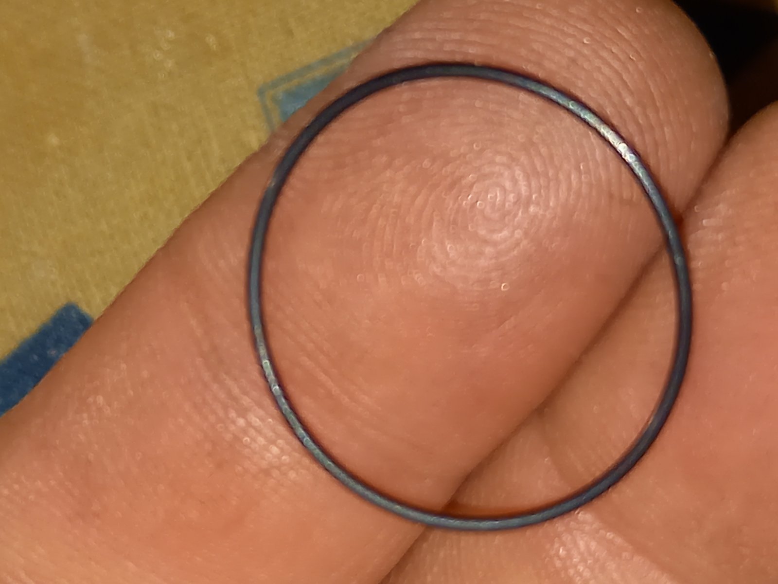
I could barely get my index finger into the bore whatsoever, so it was a lot of fussing about with one pinky and a toothpick to manipulate the rings in their slots.


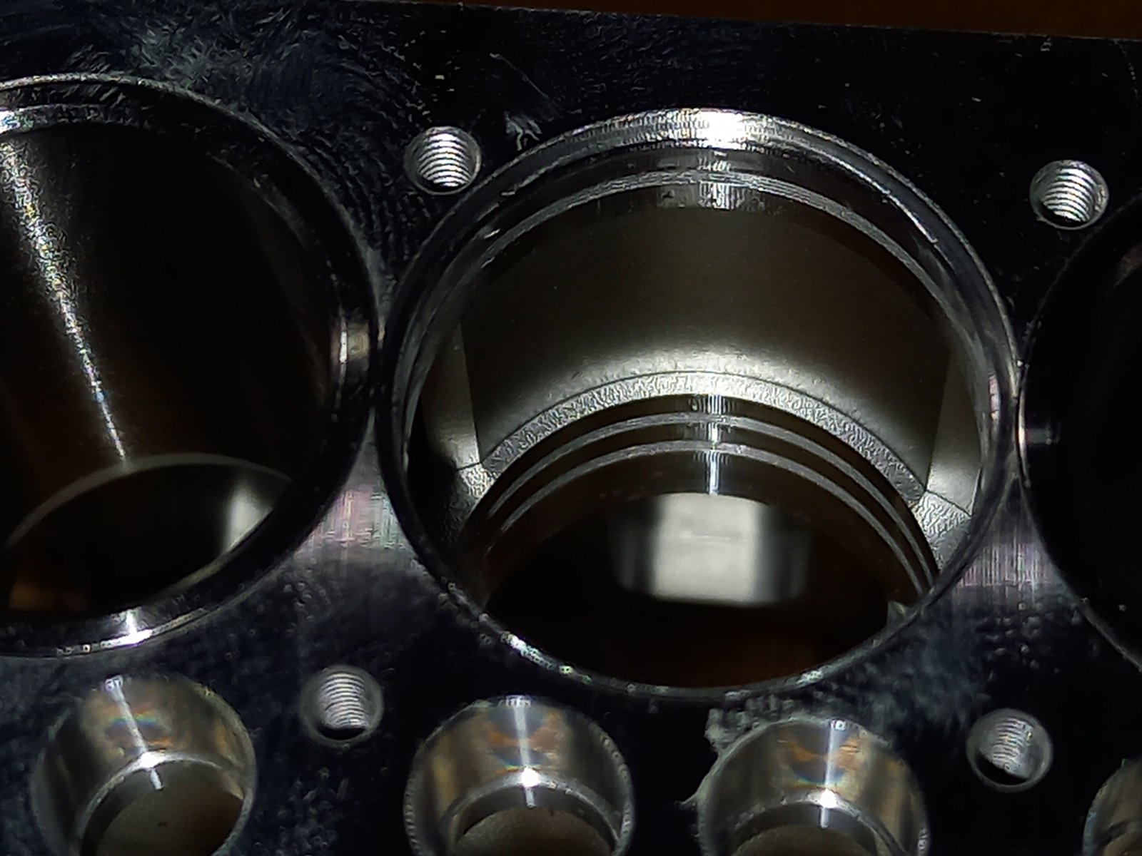
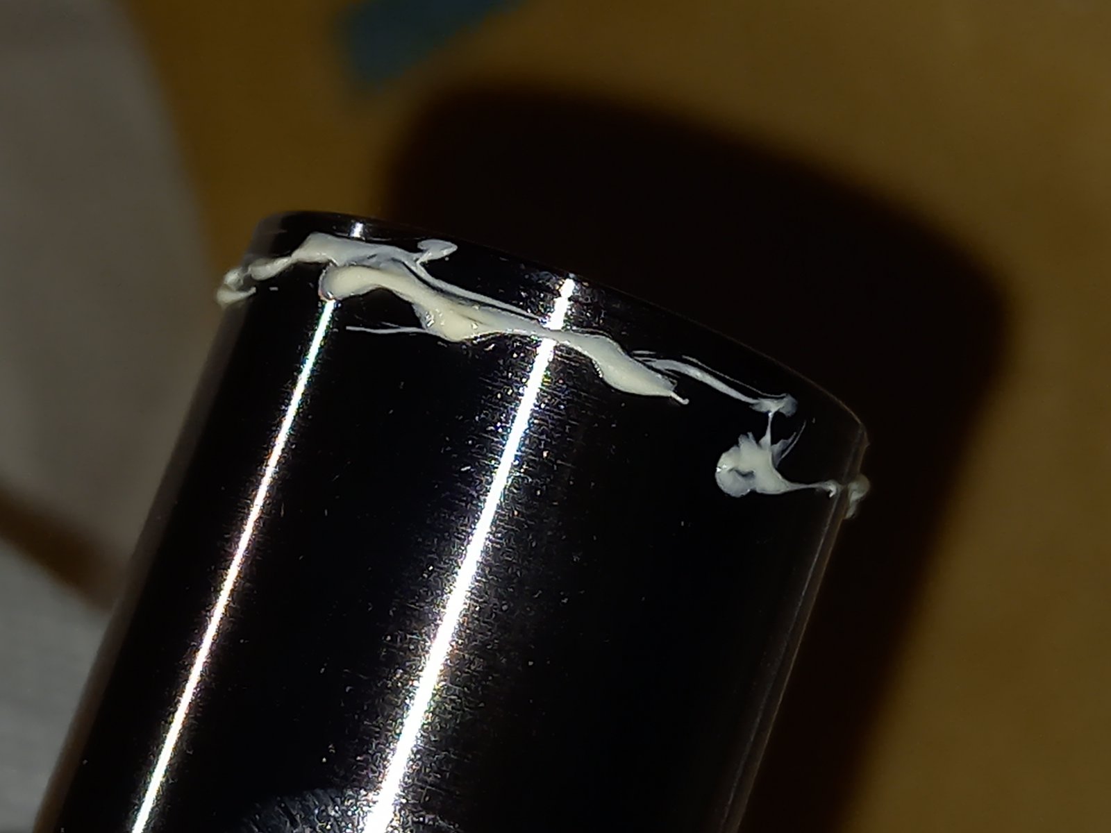
A bit of grease on the liner serves to allow the liner to be slid into the bore, and care must be taken that the bevelled edge passes the rings properly, or liner and block will act like a scissors and cut the rings.


There are 12 O-rings needed, and 13 in the kit, so you can only make ONE mistake...


Next step was the installation of crankshaft (of which I did not really take pics, sorry) but it was pretty straightforward: a ball bearing on the distribution side of the crankshaft, and since clearances are extremely tight, a bit of fiddling is needed to jiggle the crank into position.
About 5 mm before the crank is in position, the two halves of the brass support bearing heed to be placed, and although an easy understandable operation, due to the tight clearances and fit, this is a bit of a hassle. Once in place, the crank can be pushed home, and a single M3 bolt locks the support bearing assembly against rotation.
 
In my case, the crank turned over extremely smooth, no fuss, no fiddling, no search for undesirable friction.

After that, time to install camshaft and distribution.
This part is really beautifully made, with proper keyways and keys, all extremely miniature and ultra-realistic.


(the hole in the large gear has a reason: Once fitted, it is impossible to pull the gear off due to lack of purchase. The bearing of the camshaft is locked in place with two screws, so the hole serves to remove these screws, in order to pull camshaft and gear together. There are no timing marks, the keys serve that function)

This was the first point where I encountered poor fit: the keys were ever so slightly too large and I had to file them down a touch with a needle file, which is not that easy to do given that the key was about 1,5 x 1,5 x 5 mm. How do you hold that in a vise?

(you don't... between the fingertips and accept that you're going to loose a bit of epidermis on the fingertips... :p )

Then the conrods and pistons need to be joined. Another not too impressive part of the engine: According to the description, the bosses in the piston should be a bit different in diameter, with one slide fit and one press fit. The idea is to fit the gudgeon pin into the slide fit, position the small end, then carefully push the gudgeon pin home, with the addition of a bit "anaerobic 242/271" (more commonly known as "loctite" :D ).

Only one piston showed these characteristics, the other three pistons had no noticable difference in fit and were slide fits.
One of the gudgeon pins even was a tiny bit too large and I had to carefully grind that one down ever so slightly.
So I fitted all four gudgeon pins with loctite, something I raise my eyebrows over to be totally honest.
There was no space to place Teflon pads like in most normal model engines.

Oh well, nothing I can do about that...

The piston rings are pretty filigrane too, and I was worried that fitting the 2nd ring (which has to pass the first ring) would be problematic, but I was surprised how easy each ring (all 8 of them) went in their allocated slots.


Next step, the pistons need to be placed in the liners and the conrods hooked up to the crankpins.
First a drop of oil in the liner, on the piston, on the small end and the crankpin.
Next the big end bearing is opened. Care to be taken that only one rod is opened at a time so as to not mix rods and caps, because the rod and cap are paired. The caps also should be fitted in the same position as they came off, there is a tiny notch indicating that position.
The big end bearing has an oiler hole in the rod, the oiler hole should be on the side of the oil gallery.

When fitting the piston into the cylinder, the liner has a tiny bevel topside, the first ring easily slides in with a bit of pushing the ring in with a toothpick.
 
The pitfall is getting the top ring in: It just so happens that at the same point where the top ring needs to pass the top of the liner, also the conrod meets the crankwebs at the tiniest bit of misalignment. If you don't catch this interference, there is a risk of damage to the bigend bore and the landing face of the big end cap when you push too hard in an effort to get that darn ring (which is NOT the cause of resistance) into the liner.
REAL care must be taken that the rod is hanging free between the webs instead of interfering with them.
Once that hurdle is passed, pushing everything home and fitting the bearing cap is straightforward.


Now immediately it becomes clear how much friction piston rings generate: that smoothly turning crank became increasingly resistive with every piston installed.
That should cure itself during break-in I guess.

Fitting the flywheel casing (which also holds the pre-fitted DE bearing of the crankshaft, is nothing worth mentioning, and ditto the fitting of the largely pre-assembled head. I am a bit sceptical about the non-metallic head gasket, but it is what it is, more about that later.

Fitting the cam followers, pushrods and rocker arms also is very uneventful, but one thing that stood out: the designer took a shortcut for the cups holding the pushrods. Normally, pushrods are fitted with hemisphere ends, and rest in properly fitting cups. On this engine, the rods are rounded, and the cups are.... the internal hex holes of Allen head bolts... {:-{ :((
 
It will probably work just fine, but hey...???
 
The downside of this is that valve clearance probably will need frequent adjustment initially because of the rod-ends mating with the Allen heads, working their way in a bit, and that's the thing: adjustment needs to be done with needle nose pliers acting on those cups, there are no slots in the threaded ends of the adjusters.  Oh well, that 1000 Euro price HAS to come from somewhere, right?

Installing the starting gear is a real PITA, because the one way bearing in the main starter wheel is keyed to the shaft and a fairly tight fit.
Pushing this home while only being able to turn one way to align the slot, while at the same time trying to make the teeth of the intermediate gear mesh, well, it took me several hours before it suddenly and without identifiable reason clicked into place...

And that's where I have landed now...
 
 <iframe width="560" height="315" src="https://www.youtube.com/embed/h7xRAO7QpUY?si=98UIDTsX_pkxOdg6" title="YouTube video player" frameborder="0" allow="accelerometer; autoplay; clipboard-write; encrypted-media; gyroscope; picture-in-picture; web-share" referrerpolicy="strict-origin-when-cross-origin" allowfullscreen></iframe>
 
  https://www.youtube.com/watch?v=h7xRAO7QpUY
Logged
If you do without observing, you won't learn a thing.
If you observe without doing, you'll never know if what you learned was true.

1967Brutus

  • Full Mayhemer
  • *****
  • Offline Offline
  • Posts: 230
  • I am in it for the learning!
  • Location: The Netherlands, Friesland to be more exact
Re: Gasoline powered Tugboat
« Reply #45 on: March 21, 2024, 11:39:42 pm »

So on with the next steps, the fluid circulation devices (AKA "pumps").


The oil pump is a really tiny affair:


Not much to tell about it, it worked at first assembly. I am not sure if the oil flow will be sufficient, I will have to judge that at the first engine run.
Constructionwise not much remarkable about it, closed housing, single oillite bearing outside of the oil space, a shaft seal behind the oillite beearing to hold the oil in the system. In general the design is rather simple and no-nonsense.
The oil pump can pivot around its lower mounting point and doubles as a belt tensioner. The "belt" is a set of thin long O-rings


The waterpump was a different affair...
The existing design of the cylinder block was prepared to accept a direct bolt-on centrifugal waterpump that could not convince anyone with its pumping capacity, so the designer felt that a gear pump had to be fitted into the existing layout, and to be totally honest, the result is not what I would have come up with.
The pump housing consists of two parts, sealed off by a thin paper gasket, which due to the inconvenient layout of the fluid channels does not really have the simplest of shapes. Dry, it is perfectly manageable, but once fluid has been in the system, and the gasket is wet, it turns into a fragile and difficult to handle scrap of paper vaguely resembling the consistency of a boiled leaf of spinach...
Virtually all other gaskets have been stamped out of Teflon sheet, and are much easier to handle, I have no clue as to why the designer here opted for paper, it really is the wrong choice of material IMHO.

That would not be so bad if the pump could be assembled and boxed up as a separate bolt-on unit, but here is where the designers really messed up: The three bolts that hold the two pump parts together ALSO hold it to the engine block. In other words, assembly of the pump AND fitting it to the engine block are one single operation, which is made more difficult due to one of the bearings of the driven shaft being placed in the engine block and not in the pump itself. This makes it virtually impossible to keep the (previously wetted) split-gasket in its proper place while manipulating one other gasket (between pump and cylinderblock), two pump halves, a drive shaft, AND three bolts...
I normally am a fairly patient messer-abouter with teeny tiny engine parts and delicate mechanisms, but this one tested my patience and dexterity to the limit and (a touch beyond, actually)... I mean: it took me the better part of 45 minutes to assemble the pump because I kept noticing the gaskets slid out of place during assembly. A Teflon splitgasket would literally have made this job a one minute affair... :( :( :(

To make matters worse: I think Cison has some issues with their boring and drilling department, because the gear and shaft are supposed to be an interference fit. They were not... So during the initial test the pump did not work... Dammit! That's when I found out that disassembling the pump in wet condition is a nightmare.

I found the gear to be loose on the shaft, so I took the Dremel and ground a few notches in both the shaft and the gear bore, degreased the parts thoroughly, coated shaft and bore with heat-curable Epoxy (UHU Plus E300), assembled the shaft and gear taking care to properly locate the gear on the shaft, and baked it in the oven at 75 degC for about 2 hours.
The notches serve to give the Epoxy some purchase, but care must be taken that the fit is not affected, so the notches have to be very local.

This solved the issue, but the split-gasket being near impossible to locate properly during assembly, probably there was a bit of gasket stuck between the gears, which I carefully pried loose by turning the pumpshaft by hand about 10 turns.
The resulting "drill powered" testrun with liquid in the system showed a puff of dark dirt coming out with the first dash of cooling liquid from the return line.
I ran the pump like that for a few minutes, then flushed with fresh and clean fluid, and ran the pump some more.

FWIW I am using off the shelf automotive "ready to use" cooling liquid (in my case Gulf XXL, but I don't think that is really important) primarily because of its corrosion inhibiting and lubricating properties
 
https://www.youtube.com/watch?v=WQtj0qeJ4Go

At this speed, I measured a volume flow of about 100 ml/minute, and although I do not know the exact RPM of the cordless drill, I estimate it at between 1000 and 1500. The engine is intended to run 1500 governed, and given the pulley ratio (approx 2:1), I should have about double that flow in running conditions. A careful estimate would hint at a delta-T of about 15 deg C over the cylinder block.

After this "break in" the pump turned over smooth enough for not to cause slippage of the belts.

At this point in time, here's what the engine looks like right now:


Logged
If you do without observing, you won't learn a thing.
If you observe without doing, you'll never know if what you learned was true.

1967Brutus

  • Full Mayhemer
  • *****
  • Offline Offline
  • Posts: 230
  • I am in it for the learning!
  • Location: The Netherlands, Friesland to be more exact
Re: Gasoline powered Tugboat
« Reply #46 on: March 22, 2024, 01:15:44 pm »

Fitting the intake manifold was the next job and equally similar to pulling teeth...

The manifold itself is a fairly decent piece of 3D-printed metal.I have no clue how strong or brittle this stuff is, so it was out with the silk gloves...

The availlable access for tooling is minimal, the manifold is attached to the head by 8 bolts in 4 flanges, with O-rings to seal the intake tract off.
First step is to lay the engine on its side and place the O-rings in their rather shallow chambers, then fit the manifold.
In order to fit the manifold you need to first locate all 8 bolts, and those bolts are slippery, not easy to grip with pliers or pincers.

Then you need to hold the manifold with one hand in place, while the other hand needs to get each bolt going on its first thread, which is tricky because they are allen head bolts but there is only marginal access for a normal schrewdriver type allen wrench.
Only tighten the bolts one turn at a time, because screwing in the first bolt, lowers the manifold in place, and the remaining bolts now sticking out high, become unreachable for further tightening.

And all this time you HAVE to hold the manifold up with the other hand, in order to prevent dislocating one of the O-rings...


I had to shorten an old Allen Key in order to be able to reach the bolts.


The carb visually looks different from normal glow style carbs, with several things that looked like adjustment possibilities, so I had high hopes that this would be some special gasoline adapted design, but on closer examination, it turns out it is basically an old faxhioned airbleed-carb, just built a bit unusual. Not very optimistic about that, since previous experience with airbleed carbs and gasoline is not very faith inspiring.


Logged
If you do without observing, you won't learn a thing.
If you observe without doing, you'll never know if what you learned was true.

1967Brutus

  • Full Mayhemer
  • *****
  • Offline Offline
  • Posts: 230
  • I am in it for the learning!
  • Location: The Netherlands, Friesland to be more exact
Re: Gasoline powered Tugboat
« Reply #47 on: March 22, 2024, 02:32:21 pm »

There is one thing I have not yet mentioned here, which, when I found out was a bit of a bummer...

According to the info on the Stirlingkit.com page where I bought the engine, the sparkplug size was 1/4"-32, the common glow plug thread size.
Since I allready own a couple of 4-cylinder ignition sets and literally a dozen or so spare plugs (all my planes run converted ex-glow engines, among them at least one twin and a 5-cylinder radial, so one tends to keep some stock:D :D ), I ordered the engine without the starter kit that contains the ignition, plugs and a radiator, which of course I thought I would not need at all...

My dissapointment was great when I found out that during the revision of this engine, in early 2024 Cison in their infinite wisdom decided to use an even smaller spark plug, and since to the best of my knowledge those plugs are not manufactured anywhere else, Cison also is the sole supplier of this (to me unknown) plug, which seems to have something like an M5 fine thread series thread or something.
Although it is possible that these are Rimfire Viper series plugs which are supposed to have 10-40UNEF thread, that are close to 5 mm external. But I cannot find that thread size anywhere else.

Anyway, that was a bummer, but I have to say, Stirlingkit appears to be VERY customer oriented, since I posted a review of the engine mentioning that fact, and immediately (within 6 hours or so) received an e-mail, and the follow-up on that e-mail conversation was swift, to the poiint and friendly.
Can't say anything else.

But of course, now I need to wait for the plugs to arrive...

Oh well, gives me time to set up a testrig for the engine. Planning to hook up an old unused starter motor to serve as a variable load (a variable resistor should allow to it to function as a varable load...)

Logged
If you do without observing, you won't learn a thing.
If you observe without doing, you'll never know if what you learned was true.

1967Brutus

  • Full Mayhemer
  • *****
  • Offline Offline
  • Posts: 230
  • I am in it for the learning!
  • Location: The Netherlands, Friesland to be more exact
Re: Gasoline powered Tugboat
« Reply #48 on: March 22, 2024, 08:37:57 pm »

The engine assembly is done, apart from the ignition system.


The cooling pump I allready showed, here's the functioning of the lube oil pump:

https://www.youtube.com/watch?v=w5AhLWr3ksQ
 
Logged
If you do without observing, you won't learn a thing.
If you observe without doing, you'll never know if what you learned was true.

1967Brutus

  • Full Mayhemer
  • *****
  • Offline Offline
  • Posts: 230
  • I am in it for the learning!
  • Location: The Netherlands, Friesland to be more exact
Re: Gasoline powered Tugboat
« Reply #49 on: March 24, 2024, 08:39:10 am »

The engine is done, apart from the ignition. So that part of the project is temporarily halted.

Since it is crappy weather anyway, I thought I would go prepare the old hull because there's a lot to do there as well, and then I am thinking about installing a bilge cooler tube (maybe I need two, no idea yet), I need to start thinking about the rest of the cooling system (expansion tank, temperature control valve, etc etc), a fuel supply (probably a gravity feed fuel tank and a floatbowl from an old moped carb or such), exhaust system with dirt collecting tank, servo's, electricals, ballast and much more.

So I turned the hull upside down and... :(( {:-{


Looks like I need to break out the 180 grit waterproof, because that coat of paint ain't waterproof no more.

Oh well, the waterline was located wrong anyway (too low, the boat needs to be ballasted quite a bit deeper than that) and as I said, it's crappy weather, nothing better to do anyway.

Gonna be a very messy job...  <*<
Logged
If you do without observing, you won't learn a thing.
If you observe without doing, you'll never know if what you learned was true.
Pages: 1 [2] 3   Go Up
 

Page created in 0.098 seconds with 21 queries.