Dear friends
as promised or may better said as I have threatened to do, here the report of my eternal build from scratch of a sailboat with long keel based on the plan of the Voilier from a German source. The plan is the copy of a copy of a copy and as such distortions of it have made it necessary to do a lot of rework on the plan to be able to use it. I was quite disappointed when I got delivered the plan that did not consist of more than a DIN A0 sized paper.

This plan used to build the Carina is even in worse shape, as I did not care enough of it when I build the first hull using this plan the sail boat called the Sabrina. Then my son Andreas had to embarque into a school work in its 8th class and so he accepted my offer to build a hull based on this plan. For me the intention was to build a light version of the sail boat, as the first resulted too ambitious.
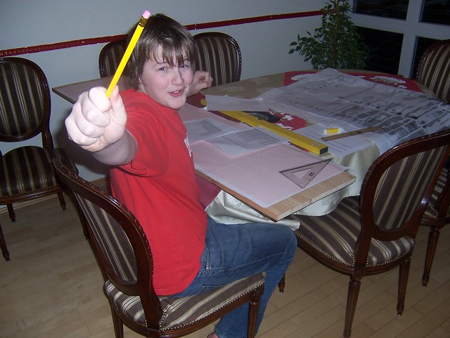
So the first step in this project for my son was to digitize the frames of the plan and the top and side views. For this he started with good old fashion technique using oil, to make the paper of the plan transparent and a needle and pass the shapes onto coordinate paper.
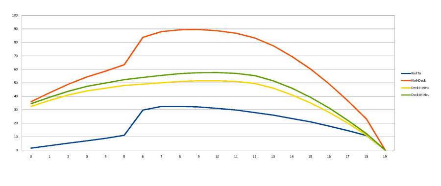
We used the Excel Chart feature, were the previously recorded digitized values were stored to fix the values that were evidently wrong. A nice side effect of this was, that errors while digitizing the data became evident and could be corrected.
Having done this we used the result to fix distorsions and to ensure the curves were smooth. Then we passes the frames into a CAD package you can get for free, called "Solid Edge 2G Drafting". Here an example: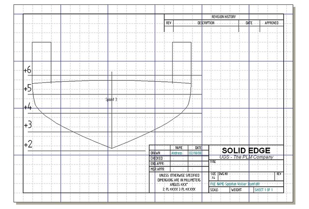
You can see that we added "ears" to the frames. The reason for this is that we choose the the upside down method of building the hull and all frames had to be placed at such altitude above the base, that the design waterline had to on a horizontal plane parallel to the base.
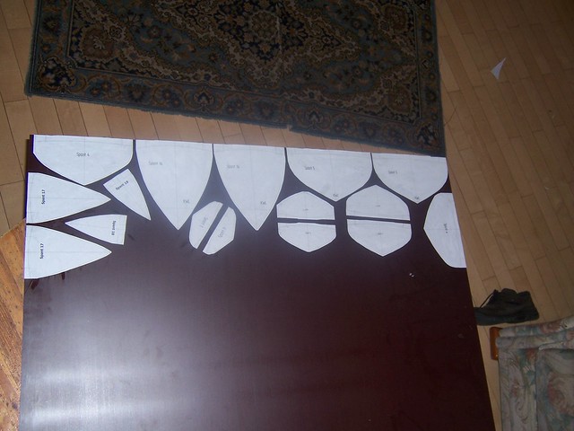
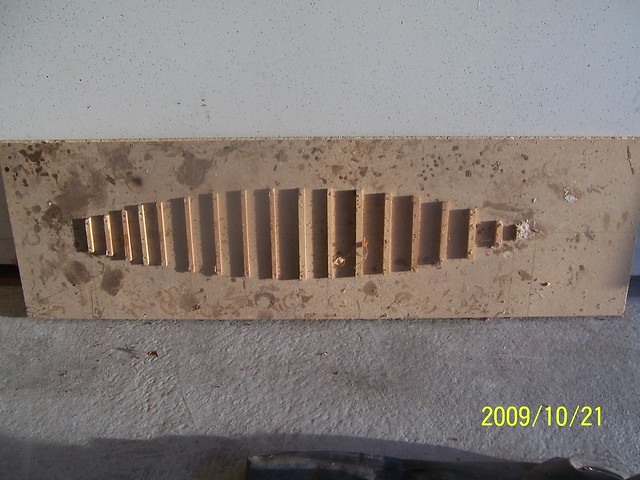
We than printed the frame images and glued them onto a 4 mm thick wooden plate. I want to indicate, that heavy paper or even better, carton should be used, as normal 80 gr. paper tends to change its shape, when the glue is applied, as it gets wet. This wooden plate used is called "Siebdruckplatte" in German. This king of wooden plate is used to build concrete formwork. It has the advantage to have a surface that is very resistant to mechanical and chemical stress, here the advantage is that it is very brittle. You will see later why this is of huge benefit!
As you might see looking in detail into the foto, I used the zip-principle to glue the ridges onto the frames, 8 x 3 mm cross section.
To ensure the hull would not be distorted during the construction, we glued the ridges, one at each side, making sure the stress would stay symmetrical.
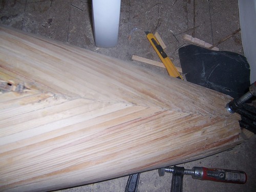
When I build my first hull I was worried about how easy or difficult the glueing of the ridges would be, specially at places like the one shown in the picture, were different shapes come together. But it proved to be no problem. The most difficult one was glueing the second ridge after the one following the deckline next to the stern mirror. The first ridge following the deckline had to be glued vertically, the second hat to follow the large change of the frame shape.
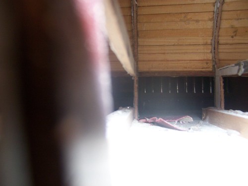
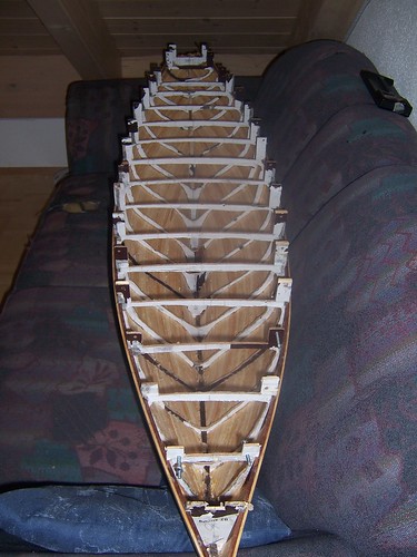
The reason I used pine wood for the ridges, was the grain of the wood. I want to highlight the old wisdom of anyone familiar with handcraft work, that any error that can be fixed early in the work process saves from having to spend 10x the effort to fix it later! So spending effort to get perfectly shaped frames is well spend to save work while grinding. my son had the great idea of taking some images from within the hull to make the construction visible. Next some pictures made from within the hull!

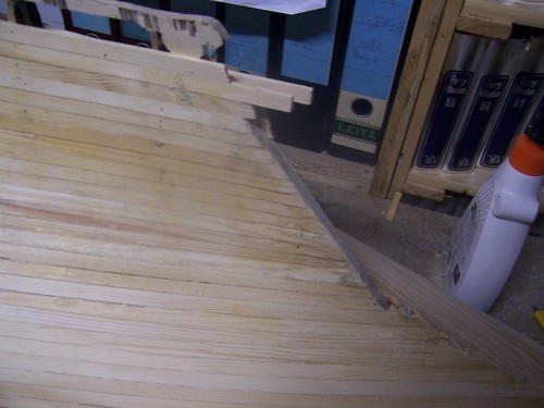
I love this picture as it shows the frames and the ridges glued to them. But also interesting has proven to be the fact that even the filigran shape of the frames was OK and it facilitates the pressing of the ridges onto the frames while glueing them.
Now a picture from the grinding phase of the construction of the hull.
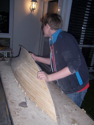
While no doubt it is a tough job, it is also honouring it with the results! excuse me if you consider it not appropriate. But sliding the hand surface of such a wooden hull after some grinding gives a wonderful feeling, some consider as great as doing the same with a woman! Wood is a wonderful material to work with! To motivate myself grinding, I like to proceed, changing from grinding one side until it feels pretty good and than change sides. The result is, that the actual side being grinded at the end feels so much better, that you end up really wishing to improve the other side! Grinding of the hull took nearly 3 weeks!
When the grinding has reached a quality of the surface that seems fine, I like to apply G8 polyurethane varnish, with thinner, using 4 parts of thinner and one part of the varnish. One one side this varnish has the effect to protect the wood from humidity that might come in touch with it if the lamination gets damaged, but in this phase of grinding the hull it has the effect of improving the light reflection of the surface of the hull making irregularities visible.
Remember, I cannot use filler, as i want to keep the grain of the pine wood visible. On the picture you see me working on removing the hull from the base. The frame had been fixed to the bars screwed onto the base, but the glue falling onto it while glueing the ridges onto the frame, made it necessary to use a tool to remove the frames. You can also see how the G8 has changed the color of the ridges, while this is also a prove that the wood is well protected against humidity, as the thinner helps the G8 varnish to penetrate deep into the wood.
Here a picture of the base showing the principle of how I fixed the frames onto it. The planarity of the base is key, as any distortion would pass onto the hull shape being build. So I use the thickest wooden plate available and do reinforce it applying stabilizing wooden frame at the length on both sides.
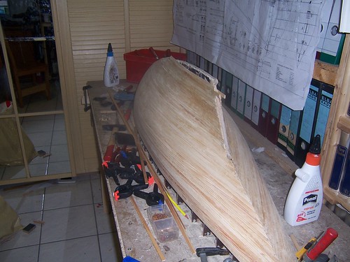
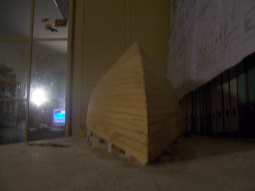
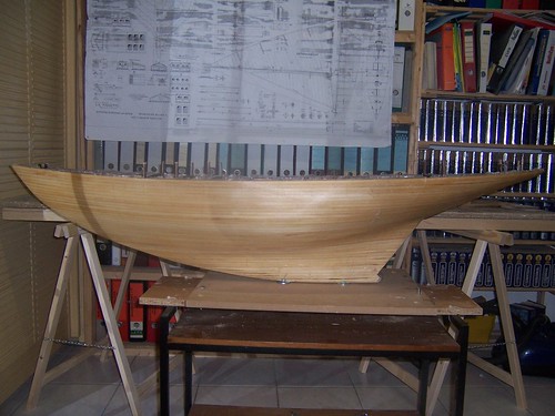
Here a view from the toüp of the whole hull, just after removing it from the base. You can see, that the frame are already implementing the curvature of the deck, a useless effort, as the frames broke easily due to the brittle nature of the wood used! The weight of this 165 cm long hull was just about 450 gr, including the frames!
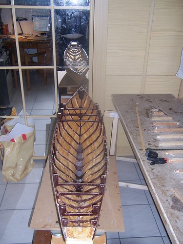
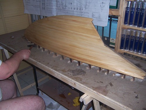
Here you can see how the frames got spoiled over time. But this apparently weakness proved to be marvelous! As the frames were so brittle, removing them, just using a tong, grasping a piece of the frame and turning the tong. This way the frames could be removed leaving nearly no trace on the hull!
Isn't this a great result? Such a clean inner side of the hull, that just required a bit of grinding, would make it much easier to laminate the hull from within. But it also reduced the weight. of course I did also apply a few layers of G8 varnish to the inner side to make sure the wood was well protected against humidity! But there are 2 more things I would like to highlight in this picture. One being the fact that I did fill up the front most and the rear most compartment made by the frame with epoxy. And that I did insert at this phase only in the front an aluminium piece in it where the screwed hole was prepared to connect the fixing point of the mast. This way that pont was firmly integrated into the hull structure. later same was done at the rear.
The second point I want to highlight is the lead I am casting into the bottom of the keel. The technique used and that prevents the wooden ridges to suffer from that process is as follows. Fist i just cast a bit into the hull and let it cool. The amount of heat energy of just a bit lead is not enough to endanger the wood. Then, as i add more lead, the already present lead works a a heat sink, absorbing the lead of the later one applied, so that on every step more and more lead can be casted into the hull without damaging the wood.
Here a more detailed view of this.
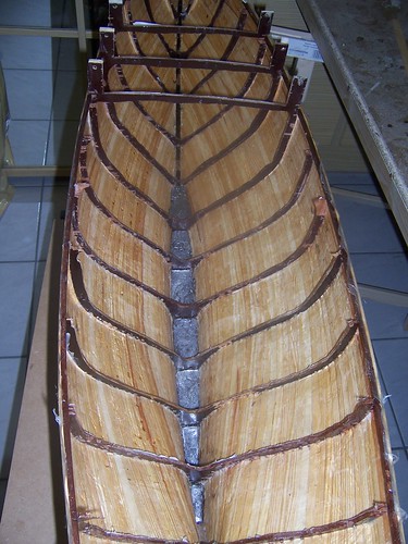
remember, that on a sail boat with long keel every effort has to be done to have the center of gravity as deep in the hull as possible. Just let me tell you, that the final displacement of the hull allows for a total weight of the sail boat of 29 kgs!
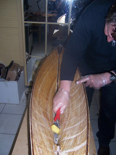
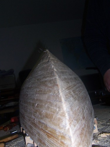
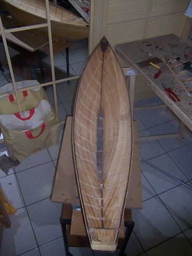
Here you see me laminating the hull with glas fiber and epoxy from within. it is important to mention, that as wood works, to prevent this from making the ridges noticeable when touching the hull from outside, symmetrical lamination from the inner and the external side of the hull is mandatory. i have used 29 grs per square meter weight glas fiber for the lamination, but up to about 100 grs is OK, and you would not see or feel the lamination when touching the hull!
Here the compensation for all those efforts! i sometimes think it would make sense to leave the hull like this, as the color is to my personal oüpinion marvelous! I want to stop here the report to reflect the achievement reached at this point and continue the report as a reply to this contribution!


 Author
Topic: Carina sailboat - my scratch build! (Read 25956 times)
Author
Topic: Carina sailboat - my scratch build! (Read 25956 times)