Model Boat Mayhem

Please login or register.

Login with username, password and session length.
Pages: 1 [2] 3   Go Down

Author Topic: Fitting out a 47: A Rivet Counter's Guide  (Read 27131 times)

heritorasphodel

  • Inactive
  • Full Mayhemer
  • *****
  • Offline Offline
  • Posts: 282
  • Location: Near Canterbury
Re: Fitting out a 47: A Rivet Counter's Guide
« Reply #25 on: January 02, 2013, 10:50:04 pm »

Since another thread has started about the 47 I thought I'd put up some more of my build, and my reference material. It's of little use to me now that the boat is gone, so I think it would be good to share it with everyone.


The way the belting is done on my boat was a bit different to others. The flange between hull and deck was cut off entirely, separating the deck and the hull, which was then fixed back on and the gap filled. Personally I think this was easier than trying to glass the join on the inside of the hull, although it probably wasn't half as strong.


The belting on mine, with the remains of the gap covered with plastic strip:


On the real boats the edge of the belting was a full half round, which could be added to the model after the flange is removed. On Frederick Edward Crick: (also in this photo is the step alongside the hull)


Andrew


Logged

heritorasphodel

  • Inactive
  • Full Mayhemer
  • *****
  • Offline Offline
  • Posts: 282
  • Location: Near Canterbury
Re: Fitting out a 47: A Rivet Counter's Guide
« Reply #26 on: January 02, 2013, 11:05:05 pm »

The next prominent feature is the large bulwarks at bow and stern. Dad built these on to the model.


First, the upright supports are cut, making sure they are far longer than they need to be. Holes are then cut into the deck, and the uprights are epoxied directly to the sides of the hull, which gives them the correct angle above the deck. The rest of the framework is then fitted, and initially a piece of thin ply was used as the face of the bulwarks. Late in their lives, some of the boat's bulwarks were painted the same blue as the hull or a light grey, so the piece of ply could just be painted and left like that, but on the earlier boats the mahogany planks were visible so I added planks of veneer stained mahogany which was then varnished.


This photo shows the arrangement of planks around the openings in the aft bulwarks. A brass fitting was fitted on the inside to strengthen it.


After this a capping strip was made from two layers of unstained veneer and varnished. All the supporting knees were made from plastic. (incidentally, all but the last two pairs of knees are perpendicular to the centreline)


On Frederick Edward Crick:


I'll try and find some photos of the construction, if there are any.
Andrew
Logged

heritorasphodel

  • Inactive
  • Full Mayhemer
  • *****
  • Offline Offline
  • Posts: 282
  • Location: Near Canterbury
Re: Fitting out a 47: The Bullnose
« Reply #27 on: January 02, 2013, 11:21:59 pm »

The last bit for tonight is the bullnose. This is a 'blinking' difficult bit to make because although it's symmetrical both sides cant out at odd angles. I built it from very thick bits of plasticard and lots of filler. The fairlead in the centre is on a brass pin to allow it to roll. I built this bit wrong, 'cos I forgot to take into account the thickness of the base of the bullnose. My effort:


Note how the thickness of the front only brings the base up to deck level. Also, there's a flange around the whole of the eye. This is the real thing:


The flange is only on the lower half of the eye, as the top can open. The base is a good 4 or 5 inches above the deck level. My effort was fairly close, but would have been one of those things to replace when I get bored with other boats.


The back of the bullnose on Frederick Edward Crick.


Andrew
Logged

vnkiwi

  • Full Mayhemer
  • *****
  • Offline Offline
  • Posts: 1,593
  • Location: SE Asia
Re: Fitting out a 47: A Rivet Counter's Guide
« Reply #28 on: January 02, 2013, 11:48:34 pm »

Hi Andrew (heritoraphodel),
Very good to see you continuing with your thread on your research and build for the 47.  :-))
Don't worry any re the off-thread remarks, in my opinion all research, especially with comparison photos between model and original boat is always welcome, even your opinions re possible faults and/or differences in fibreglass hulls (which sometimes happen to ease manufacture). We all have modified for easier build at some stage or other.   ;)
It always comes down to our own personal choice as to how, and what we build, and if its "wrong" in the eyes of the other rivet counters, does it matter, as long as we are happy with the end result.
I to am a rivet counter in my research, but choose what to include on my models. Doesn't make them wrong, just fit for purpose.
Just my opinion.
Keep up the good work
vnkiwi
 :}

Logged
If it ain't broke. Don't fix it !

heritorasphodel

  • Inactive
  • Full Mayhemer
  • *****
  • Offline Offline
  • Posts: 282
  • Location: Near Canterbury
Re: Fitting out a 47: A Rivet Counter's Guide
« Reply #29 on: January 02, 2013, 11:54:04 pm »

Thanks, I just wish I could do more, except some nasty so-and-so decided that they would rather have my boat and lifted it from my shed...  >>:-(

Question is, do I get another one or hope this one comes back?

Andrew
Logged

vnkiwi

  • Full Mayhemer
  • *****
  • Offline Offline
  • Posts: 1,593
  • Location: SE Asia
Re: Fitting out a 47: A Rivet Counter's Guide
« Reply #30 on: January 03, 2013, 12:00:10 am »

Andrew, very sorry to hear that.
Theiving sods everywhere. (spell check not working)
How about building a new one and showing us how again
Your research and build is a valuable reference for others future builds.
Like the lifeboats, but don't have these types down here in NZ
cheers
vnkiwi
Logged
If it ain't broke. Don't fix it !

RAAArtyGunner

  • Full Mayhemer
  • *****
  • Offline Offline
  • Posts: 3,817
  • Location: Brisbane, Australia
Re: Fitting out a 47: A Rivet Counter's Guide
« Reply #31 on: January 03, 2013, 12:05:55 am »

Andrew, very sorry to hear that.
Thieving sods everywhere. (spell check not working)
How about building a new one and showing us how again
Your research and build is a valuable reference for others future builds.
Like the lifeboats, but don't have these types down here in NZ
cheers
vnkiwi

Andrew,
 
From across the pond I also agree, we also do not have them types.  :-)) :-)) :-))
Logged
Gunna build those other boats one day.

heritorasphodel

  • Inactive
  • Full Mayhemer
  • *****
  • Offline Offline
  • Posts: 282
  • Location: Near Canterbury
Re: Fitting out a 47: A Rivet Counter's Guide
« Reply #32 on: January 03, 2013, 12:13:08 am »

I think a fair few ended up over there after service though...


I'd love to build another one, but I think I might get moaned at (I have 3 working boats in 1:12 on the go and 3 display boats in 1:24 - all lifeboats  :embarrassed: ) but I think the 47 is my favourite type of boat.


Andrew
Logged

Norseman

  • Full Mayhemer
  • *****
  • Offline Offline
  • Posts: 3,466
  • Location: Huyton, Liverpool
Re: Fitting out a 47: A Rivet Counter's Guide
« Reply #33 on: January 03, 2013, 12:22:41 am »

Question is, do I get another one or hope this one comes back?

Sorry to hear about the theft Andrew. Bryan Young had two boats stolen but got them back twelve years later (they had remained fairly local) he will be refurbishing soon.

Re research - I think it's half the fun. Compromises on build versus your findings aren't invalid and certainly better than a punt in the dark. Build threads that show the research benefit all and should be applauded.

Regards Dave.
Logged

heritorasphodel

  • Inactive
  • Full Mayhemer
  • *****
  • Offline Offline
  • Posts: 282
  • Location: Near Canterbury
Re: Fitting out a 47: A Rivet Counter's Guide
« Reply #34 on: January 03, 2013, 01:09:40 am »

Quote
Compromises on build versus your findings aren't invalid and certainly better than a punt in the dark.


I'm not sure which bit I like more, the research or the building! I completely agree with you, it's just sometimes a bit can be close to the real thing, and you think that only someone who is as obsessive as you are will know it's wrong, but then you find some new evidence and just maybe you could do a little better. After all, that's how we improve!


Andrew
Logged

vnkiwi

  • Full Mayhemer
  • *****
  • Offline Offline
  • Posts: 1,593
  • Location: SE Asia
Re: Fitting out a 47: A Rivet Counter's Guide
« Reply #35 on: January 03, 2013, 02:12:19 am »

Andrew, full agree with you   :-))
We never stop learning.    O0
As to improving, well I like to think of life as a good wine, improves with age, even if it mellows a little on the way  %)

cheers   ok2
vnkiwi
Logged
If it ain't broke. Don't fix it !

heritorasphodel

  • Inactive
  • Full Mayhemer
  • *****
  • Offline Offline
  • Posts: 282
  • Location: Near Canterbury
Re: Fitting out a 47: The Deck
« Reply #36 on: January 03, 2013, 03:03:31 pm »

The boats were built with a timber deck, simply painted grey, with thin anti-slip bars either side of the samson post, between the superstructure and the survivor's cabin hatch, either side of the superstructure at the wheelhouse doors and either side of the aft cockpit. In addition, there were anti-slip bars on the aft survivor's cabin roof.


Midway through their lives, the bars on the cabin roof were changed to a continuous patch, and later the deck was entirely covered in Treadmaster diamond pattern rubber anti-slip matting.


On my model, I had the fibreglass deck, and so I planked on top of that with brown paper to simulate the planks.


Once the planking was finished, I painted it Humbrol 79, which matches up to the colours seen on photographs. Then I imitated the caulking by using black pen between the planks. (I've now found it works better if you mark the caulking THEN paint the deck)


At this point I don't have any anti-slip on the deck.


The real thing:


Andrew

Logged

heritorasphodel

  • Inactive
  • Full Mayhemer
  • *****
  • Offline Offline
  • Posts: 282
  • Location: Near Canterbury
Re: Fitting out a 47: Deckplates
« Reply #37 on: January 03, 2013, 03:17:10 pm »

While on decks, these are the deckplates, used to access the fuel tanks, to fit pumps, etc.


These are a set of resin castings that my dad made, about a half-inch across. They are painted using brass paint, then humbrol 33 (Matt black) which is wiped off leaving it in the recesses. (NB - This is only good for fittings that are fairly well polished. Brass and bronze on lifeboats tarnishes fairly quickly, and as these are on the deck they get very filthy and are virtually impossible to clean. Therefore they could be painted brass and then grey, with bits of grey scraped off to simulate wear.)


These are on my Liverpool


Andrew


Logged

heritorasphodel

  • Inactive
  • Full Mayhemer
  • *****
  • Offline Offline
  • Posts: 282
  • Location: Near Canterbury
Re: Fitting out a 47: Superstructure
« Reply #38 on: January 03, 2013, 03:31:16 pm »

Due to a bit of damage, the original fibreglass superstructure was thrown away and a replacement made from ply.


The panel lines were added using several layers of masking tape to form an edge, and then applying filler up to the line. The filler was sanded back to the tape, which was removed to reveal a raised line. The bolts were added using blobs of PVA. On later boats the aft cockpit was covered over.


Andrew
Logged

heritorasphodel

  • Inactive
  • Full Mayhemer
  • *****
  • Offline Offline
  • Posts: 282
  • Location: Near Canterbury
Re: Fitting out a 47: The aft handrail
« Reply #39 on: January 20, 2013, 10:47:12 am »

One of the features of the larger traditional lifeboats was the handrail on the aft edge of the superstructure. Usually during a slipway launch, if the crew weren't in the aft cabin then they would stand in the aft cockpit, and therefore this handrail was fitted to the full width of the superstructure (Unlike some of the other classes, but that's another story).


As you can see there's a support frame that runs around the bottom edge of the handrail. I found it helps to fit this first as it gives the bottom of the rail an area to rest on while the glue dries.


On mine the rail itself is brass rod, while the framework is styrene, superglued to the brass to make sure it keeps it's shape. The cut outs in the framework I initially cut rectangular, and then filed out the ends to round when it was fixed.


The bulkhead on the superstructure was sanded and filled until it was flush with the rail. The lack of a handhold in the centre of the rail is due to the sternlight which was mounted on a frame above it.


Andrew
Logged

heritorasphodel

  • Inactive
  • Full Mayhemer
  • *****
  • Offline Offline
  • Posts: 282
  • Location: Near Canterbury
Re: Fitting out a 47: The forward hatch
« Reply #40 on: January 20, 2013, 10:59:31 am »

Another feature of this type is the shielded hatch on the foredeck which led to the forward survivors' cabin.


The base for this hatch is moulded on to the deck of this model, which is fairly handy, but the shield itself isn't. It's a fairly complex shape, which I think would lend itself to vacuum forming, but dad built this one, and did if fairly well, I should say. The way he built it was to make the front and sides from flat sheets of ply, and the corners from shaped pieces of balsa. A bit of plastic half-round was glued round the edge. I was a bit sceptical after hearing this, but here is the result:


On the photo you can see the corner section, but you couldn't on the actual model. I'll go into the details later.


Andrew
Logged

heritorasphodel

  • Inactive
  • Full Mayhemer
  • *****
  • Offline Offline
  • Posts: 282
  • Location: Near Canterbury
Re: Fitting out a 47: Painting
« Reply #41 on: January 20, 2013, 11:12:12 am »

After all the permanent fixtures of the boat were fitted, then it was painted.


The colours used were, (All spray paint, Halfords except where mentioned):


Superstructure and above deck fittings: Ford Polar Grey, matched to photographs and RNLB Susan Ashley.
Inside of bulwarks: Humbrol German Grey (It could be any grey, as long as it's darker than the deck)
Hull Blue: Ford Balliol Blue (A trade name for Oxford Blue)
Belting Red: Ford Sunburst Red over red primer
Hull White: Appliance Gloss White
Brass and bronze: Plastikote Brass Spray


Andrew
Logged

heritorasphodel

  • Inactive
  • Full Mayhemer
  • *****
  • Offline Offline
  • Posts: 282
  • Location: Near Canterbury
Re: Fitting out a 47: The Name
« Reply #42 on: January 20, 2013, 11:32:40 am »

I put the name on the boat to convince me that I was getting somewhere:


The letters are vinyl from Barry's model lettering (Excellent service by the way), the larger letters being 6mm and the smaller 5mm. I've found that most models tend to have fairly large names on them, when on a lifeboat the name is normally fairly understated. The station name was later changed to "THURSO LIFE-BOAT" as I've found this format on several other boats of the class.


At this stage I didn't put the flag on because I personally feel that should be one of the last jobs, as the boat's 'acceptance into the fleet'.


Andrew
Logged

heritorasphodel

  • Inactive
  • Full Mayhemer
  • *****
  • Offline Offline
  • Posts: 282
  • Location: Near Canterbury
Re: Fitting out a 47: The Samson Post
« Reply #43 on: January 20, 2013, 11:41:09 am »

All lifeboats are fitted with a Samson post on the foredeck in some shape or form. As the name suggests, this was a strong point, often extending below the deck. On boats that were kept afloat the Samson post was also used to hold the forward mooring, when a large collar was fitted to the post. Boats on a slipway didn't have these.


This one on Frederick Edward Crick has the collar.


The model post was made from sections of dowel and plasticard for the base. It was painted in grey primer to simulate worn galvanising.


Andrew

Logged

heritorasphodel

  • Inactive
  • Full Mayhemer
  • *****
  • Offline Offline
  • Posts: 282
  • Location: Near Canterbury
Re: Fitting out a 47: The Quarter Posts
« Reply #44 on: January 20, 2013, 11:59:04 am »

The quarter posts are similar to the samson post, in that they extend below the deck. They were also used for towing.


There's a brass hook on the front of the post to prevent cables from coming off the top.


The model posts were cut from balsa, to patterns taken from the drawings. The base was shaped on the boat, and a thick plastic base fitted. This was to simulate the socket that the post sits through. The corners of the post were removed and replaced with plastic strip and then shaped, and a plastic cap was fitted. The bare wood was stained teak and then varnished, while the plastic was painted brass. They were removable, with a brass pin through the base into the deck.


Andrew
Logged

heritorasphodel

  • Inactive
  • Full Mayhemer
  • *****
  • Offline Offline
  • Posts: 282
  • Location: Near Canterbury
Re: Fitting out a 47: Haul-up Cleats
« Reply #45 on: January 20, 2013, 12:08:53 pm »

Another feature fitted to the aft deck were the haul-up cleats. I am unsure what these were for exactly, although by the name I assume to hold the boat, along with a cable through the aft ruffle holes, while it was on the slipway. If anyone has any better ideas, please let me know. Also, if anyone has a way of modelling these, I'd be interested as I've two other boats that need these fitted. The real ones are solid bronze.


Andrew
Logged

heritorasphodel

  • Inactive
  • Full Mayhemer
  • *****
  • Offline Offline
  • Posts: 282
  • Location: Near Canterbury
Re: Fitting out a 47: Hatchway Details
« Reply #46 on: January 20, 2013, 01:13:43 pm »

All of the 47s had lifelines running forward from the superstructure to the forward hatch. On some of these boats the lifelines were supported by stanchions on the forward superstructure to rings on the hatch shield. Other boats, like Pentland, had a tall frame to bring these lifelines to head height, presumably so you could pass under them rather than having to step over them. Here is Pentland's:


And mine:


Mine was made from folded brass tube, with the supports also from brass and soldered on. There are three rings on this frame, two just above the supports for the lifelines, with another on the centreline of the boat on the top rail for the forward mast stay. In rivet-counter mode, the loop has a single bolt fixing the bottom on, while the aft supports have two. There are also two brackets either side on the main loop.


Other details on the hatch shield are the Loudhailer socket, seen on the front of the shield, and the framework around the bottom of the shield that holds the hatch onto the deck. These were created from styrene, with PVA boltheads. The colour of the framework at the bottom was a sort of reddish-purple in the earlier period. I never did find the right colour.


Andrew


(PS - on some boats the frame was Barnett-style. On some of the early 52ft Barnetts, the mast folded forward, so there was no crossbar to the frame, but two reinforcing bars instead. I'm not sure why it was used, because all Watsons had aft-folding masts. If anyone knows why...)


This is the Jeannie.


Andrew
Logged

heritorasphodel

  • Inactive
  • Full Mayhemer
  • *****
  • Offline Offline
  • Posts: 282
  • Location: Near Canterbury
Re: Fitting out a 47: Superstructure Patch
« Reply #47 on: January 20, 2013, 01:35:06 pm »

In the late 60s to early 70s the RNLI experimented with high visibility paint on the boats, inspired by 44-001, the American-built 44 footer that arrived painted white. Other, older, boats had patches of their superstructure painted hi-vis orange, which became the standard. Some 47s had the aft casing and the roof painted orange, such as Pentland. I thought I'd build her at this mid period, as I've only ever seen 47s as built or completely orange. Besides, I think it looks better  :-))


Using photographs, the size of the patch was worked out. However, over this was an anti-slip patch.


This was painted with the Aged Iron textured spray paint, and was left unfinished because my painting is atrocious (overspray got everywhere) I was going to wait and then paint it Humbrol 79 to match the deck.


The lights in the top of the aft superstructure were made from a disc of plasticard with thin plastic rod fixed to it to represent the guard rails. They were painted to match the colour they were fixed to. (the aft 4 are unpainted). Also visible is the initial stages of the radar mast. I'll do this next.


Andrew
Logged

heritorasphodel

  • Inactive
  • Full Mayhemer
  • *****
  • Offline Offline
  • Posts: 282
  • Location: Near Canterbury
Re: Fitting out a 47: The Radar Mast
« Reply #48 on: January 20, 2013, 02:00:51 pm »

When the large lifeboats were initially fitted with radar, the mast was on the centreline. However, if the boat was fitted with an airbag when it was modified to self-righting then the mast was either moved to the port side or fitted to the roof. The boats that were built for slipway stations had a folding mast so the boat could fit in a low boathouse, while those built to stay afloat had fixed masts fitted.


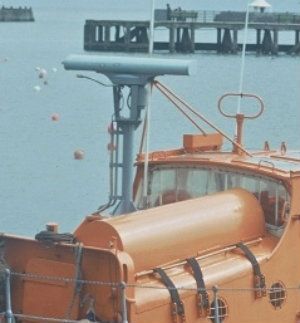
This is the fixed mast as fitted to Frederick Edward Crick. Unfortunately, as the radar mast was not an as-built fitting, it doesn't appear on any General Arrangement plans. Also, I've not found any official RNLI drawings either. Therefore the dimensions for the folding mast were taken off the mast fitted to RNLB North Foreland, a 46ft 9in Watson, as it was the same fitting.


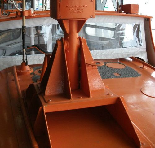
Here is mine after painting:


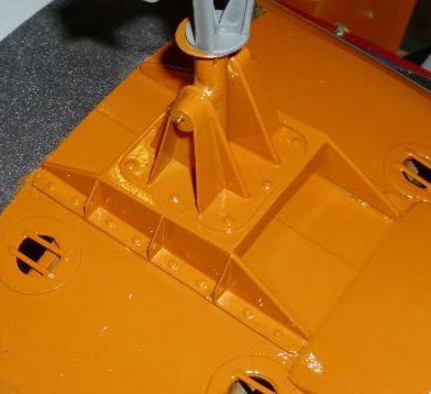
And here's a slight problem I found after carefully painting both the mast and the surface it sat on. On the real boat, as the two fixing rails of the mast are flat, and they're fitted to a curved surface, there is a black gunk that's used to fill the gap. Now, trying to be smart, I put cling film over the boat to protect the paint, put a layer of filler onto the cling film and pushed the mast onto it, to get the right curvature. What I didn't know was that after the filler had set, and I tried to pull it off, the filler had EATEN AWAY THE PAINT beneath it. I had to remove the whole area and repaint it. I didn't try that again.


By the way, if anyone wants a copy of the drawings of the mast and the radar I can have them scanned and email them.


Andrew
Logged

gribeauval

  • Full Mayhemer
  • *****
  • Offline Offline
  • Posts: 1,084
  • Tidy Bench -Tidy Mind, Messy Bench - BUSY!!
  • Location: Wakefield West Yorkshire
Re: Fitting out a 47: Haul-up Cleats
« Reply #49 on: January 20, 2013, 05:12:47 pm »

Another feature fitted to the aft deck were the haul-up cleats. I am unsure what these were for exactly, although by the name I assume to hold the boat, along with a cable through the aft ruffle holes, while it was on the slipway. If anyone has any better ideas, please let me know. Also, if anyone has a way of modelling these, I'd be interested as I've two other boats that need these fitted. The real ones are solid bronze.


Andrew


The haul up cleats are used to make the initial recovery of the boat after it had been veered down onto the bottom of the slipway. Part way up the boat is held by quarter strops and the winch wire moved onto the release pin at the base of the stern followed by rehousing of the boat ready to launch again.


This clip of my son doing this with a Tyne I built shows how it was done.


http://www.youtube.com/watch?v=CQPuo6P4NZs


Mike
Logged
True Lifeboat Nutter!!
Pages: 1 [2] 3   Go Up
 

Page created in 0.328 seconds with 18 queries.