


Ive finished the scratch built railings , they have been dry fitted so i can take a picture and give my self a pat on the back
 , heres a couple of pictures, oh and meet the new crew member i had made.
Trucker
|
61
on: September 18, 2025, 04:47:09 pm
|
||
| Started by Trucker - Last Post by Trucker | ||
|
Hello to every one
Ive finished the scratch built railings , they have been dry fitted so i can take a picture and give my self a pat on the back , heres a couple of pictures, oh and meet the new crew member i had made.Trucker |
||
|
62
The Shipyard ( Dry Dock ): Builds & Questions / Working Vessels / Re: Mark's "Le Rochefort" Build 1/24 Scale
on: September 18, 2025, 04:23:47 pm
|
||
| Started by Mark T - Last Post by Mark T | ||
|
Another update from me - you can tell I'm off work sick with all of these updates
 So I've been planking between the stern mouldings and then getting on with the nailing 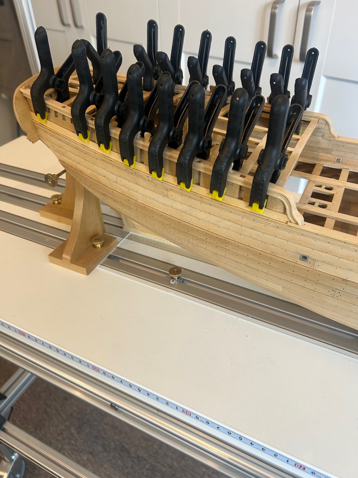 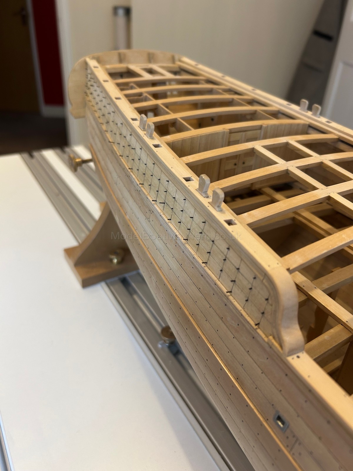 And now at last we have a stern that looks solid  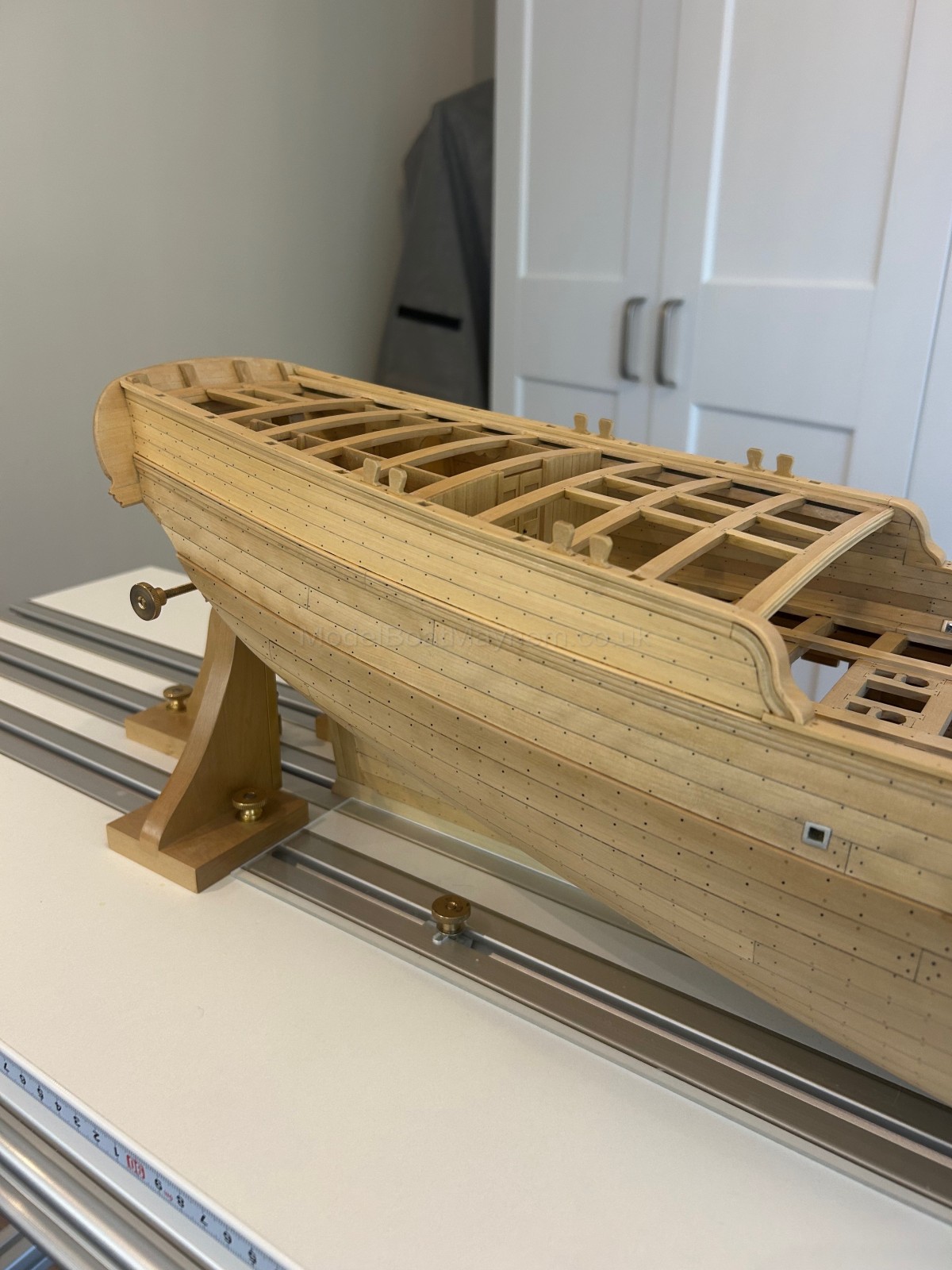 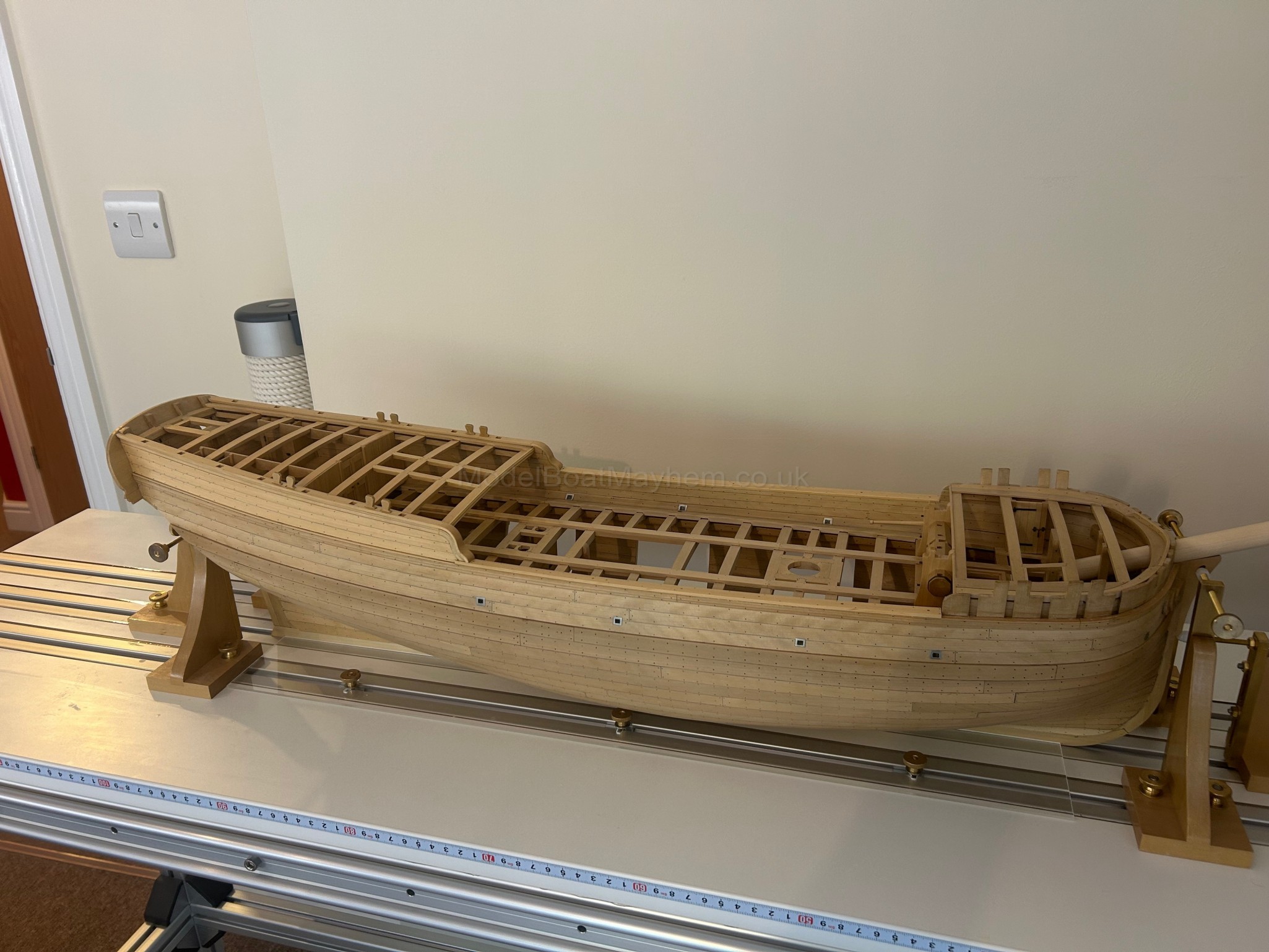 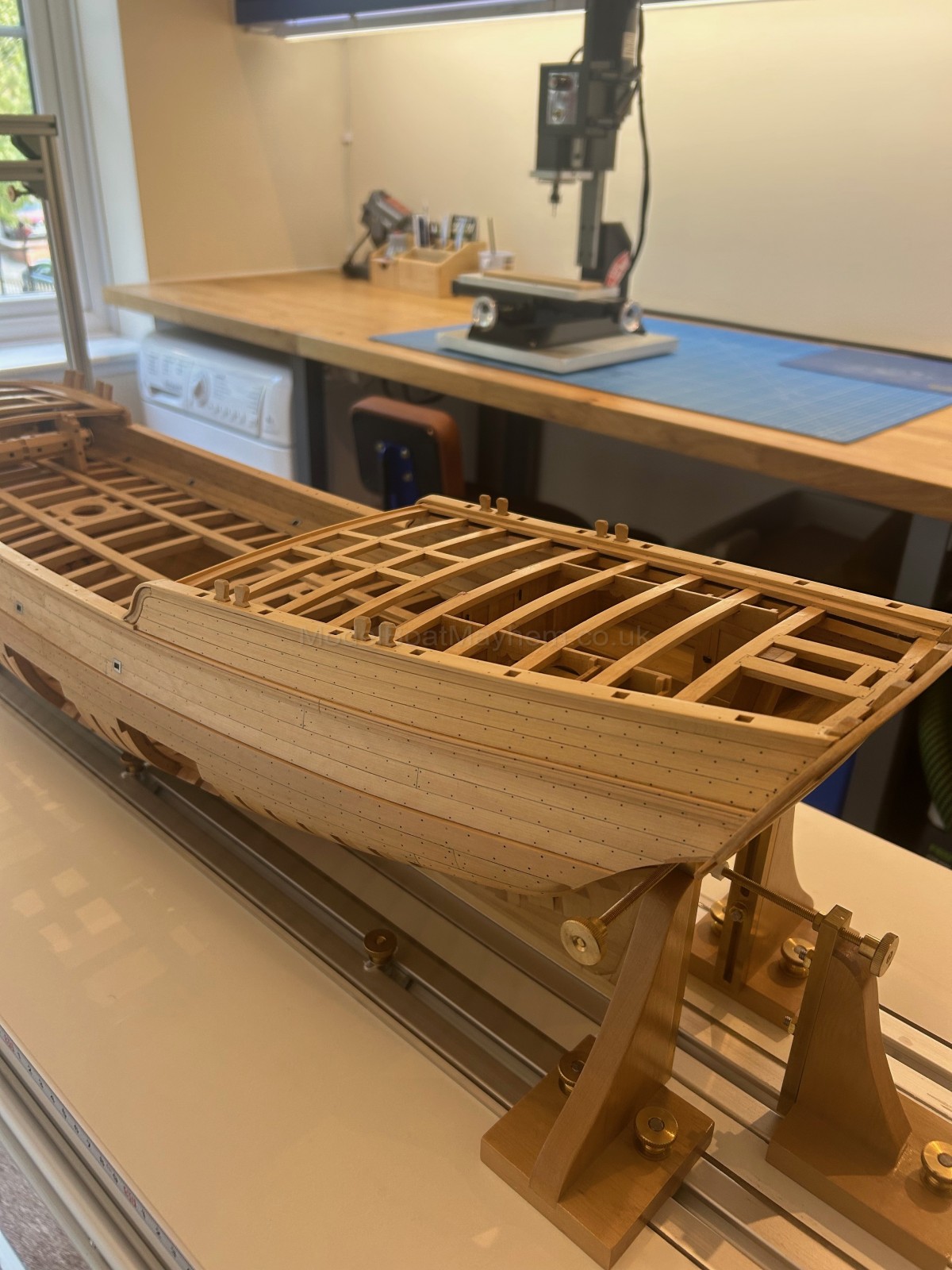 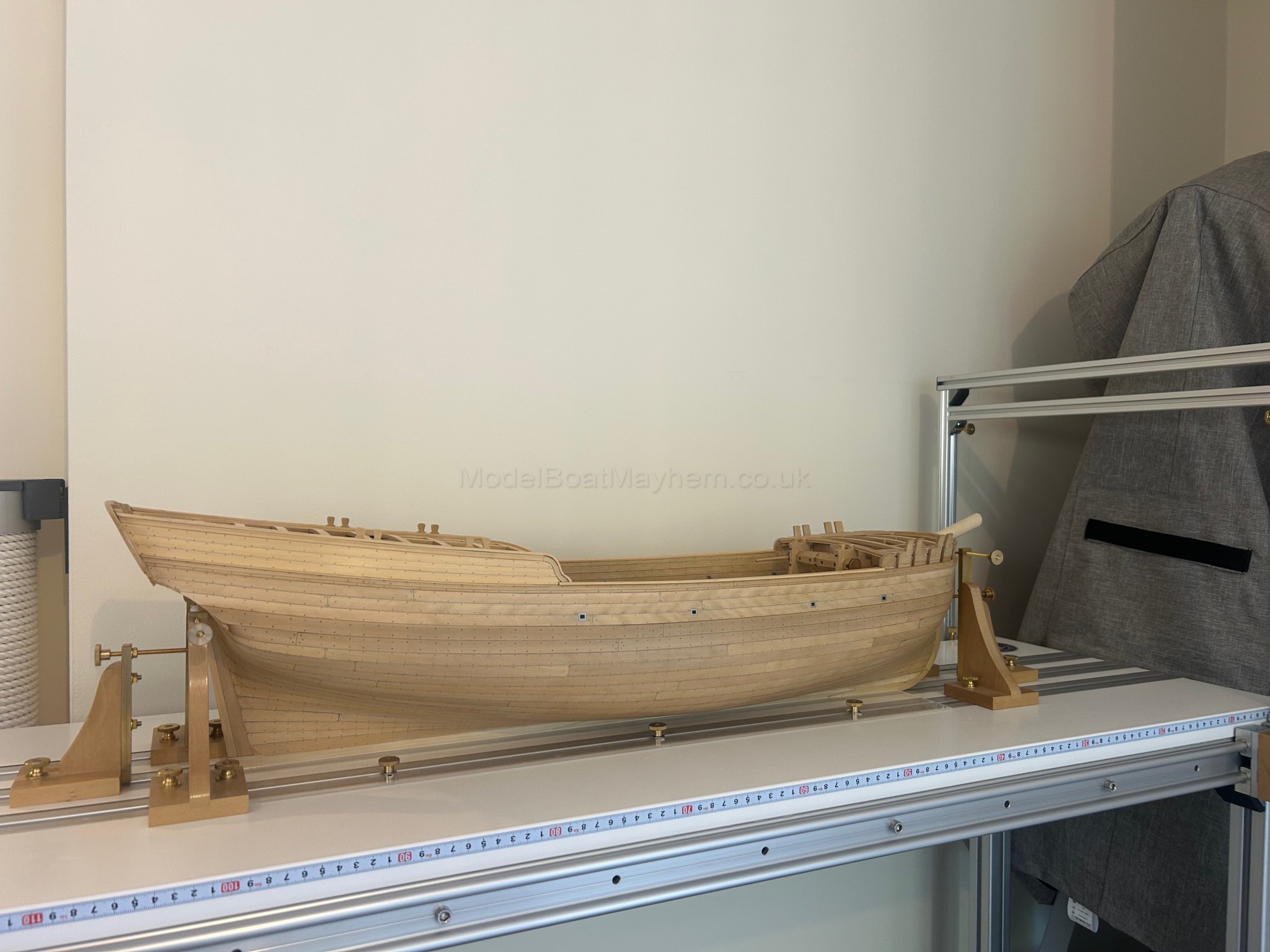 Finally I made and fitted the decorative moulding that covers the 1st beam on the quarter deck 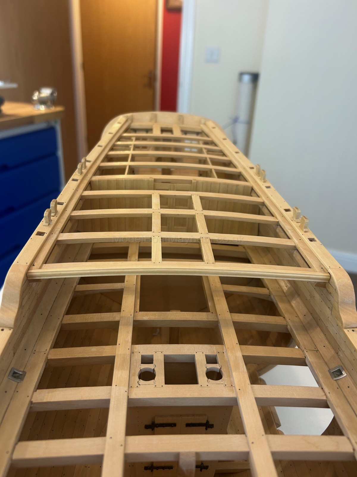 My next job is to make the gratings - I'm just waiting on the guy who made the drawings I'm working from to confirm that I have read them correctly. Cheers all - Mark |
||
|
63
Technical, Techniques, Hints, and Tips / The "Black Arts!" ( Electrics & Electronics ) / Re: Flashing blue light
on: September 18, 2025, 04:00:15 pm
|
||
| Started by SimonCornes - Last Post by Colin Bishop | ||
|
Is this what you meant Simon?
https://www.railwayscenics.com/diffused-blue-flashing-with-integrated-chip-p-3900.html#description Colin |
||
|
64
Technical, Techniques, Hints, and Tips / The "Black Arts!" ( Electrics & Electronics ) / Re: Flashing blue light
on: September 18, 2025, 01:52:55 pm
|
||
| Started by SimonCornes - Last Post by Stavros! | ||
|
https://www.componentshop.co.uk/voltage-reducer.html
Well if i can use one anyone can solves all the problems.....I use then on my model railway and power up 40 odd leds inc 4x blue flashing leds and they will run all day at a railway show Stav |
||
|
65
Technical, Techniques, Hints, and Tips / The "Black Arts!" ( Electrics & Electronics ) / Re: Flashing blue light
on: September 18, 2025, 01:35:10 pm
|
||
| Started by SimonCornes - Last Post by SimonCornes | ||
One of the ebay links shows a circuit diagram which looks a bit odd. The 4017 chip is used in a very strange way, it's flashing one bank of LED's on and off 3 times then the other bank 3 times. This may be because it's overdriving them at 12v and giving a cooldown period. One LED, flash rate about once a second. Well more like one second 'on' and one second 'off', maybe a bit less but pretty much to match a standard blue light. It seems very simple to me but if its electronics then I expect it isn't, thats why I wondered if I could by a module off the shelf with a light on one end and a power lead on the other! |
||
|
66
Technical, Techniques, Hints, and Tips / The "Black Arts!" ( Electrics & Electronics ) / Re: Flashing blue light
on: September 18, 2025, 01:30:45 pm
|
||
| Started by SimonCornes - Last Post by SimonCornes | ||
I added a link to a simple astable circuit as you were typing. Unfortunately I'm not an electronics expert like you! I can quite happily build Maplins and Action electronic kits but after that it all goes over my head ! Hopefully the kit as provided will do what I want? My intention is to not fit any LED's apart from a flylead from one of the blue LED positions which can then go to the single light I need for the boat. Goodness knows where the power supply for this board attaches but I have a PP3 connector on a lead I can use so that shouldn't be a problem |
||
|
67
The Shipyard ( Dry Dock ): Builds & Questions / Navy - Military - Battleships: / Re: 1/96 HMS Alacrity Type 21
on: September 18, 2025, 12:17:56 pm
|
||
| Started by T888 - Last Post by Detomo | ||
Cheers , shall be looking froward to more pic's  |
||
|
68
Technical, Techniques, Hints, and Tips / The "Black Arts!" ( Electrics & Electronics ) / Re: Flashing blue light
on: September 18, 2025, 08:26:59 am
|
||
| Started by SimonCornes - Last Post by HMS Invisible | ||
|
I added a link to a simple astable circuit as you were typing.
The kit has all the components to drive a blue led apart from ~33 ohm that fixes a constant current of (0.6/33) or ~ 20mA. |
||
|
69
Technical, Techniques, Hints, and Tips / The "Black Arts!" ( Electrics & Electronics ) / Re: Flashing blue light
on: September 18, 2025, 08:01:51 am
|
||
| Started by SimonCornes - Last Post by SimonCornes | ||
|
Well I ordered one last night anyway. Thats because I realised that a PP3 is 9v so Ive got around that problem. I only want one LED of course so Ill just solder a fly lead to one of the blue LED positions on the circuit board and then see what happens. Im hoping that it will just work and then i can play with the flash rate using the pot. Or is it not as simple as that? I like simple !
|
||
|
70
The Shipyard ( Dry Dock ): Builds & Questions / Navy - Military - Battleships: / Re: 1/38 super-Guardian class patrol boat,3D printed kit build
on: September 18, 2025, 04:32:33 am
|
||
| Started by Backerther - Last Post by Backerther | ||
|
In order to get the hull looked more shapely, I just cut out the wave-shield like frame partially of the portside foredeck as seen in the pics below. I personally think it better by the elimination of the part since the foredeck turns out to be sharp and shapely than starboard still left unchanged.
  Another significance to eliminate the part is intended to give a scheduled dual-purpose gun a required firing angle against the air and the surface targets. Well then, let's go to the starboard as well.!!!!  |
||