|
Schnellboot -
My Build of Jack's Robbe S130. Part 4 - It's Alive! |
||
| Index 1 2 3 4 5 6 7 8 9 10 11 12 13 14 Links | ||
Click photos to
enlarge.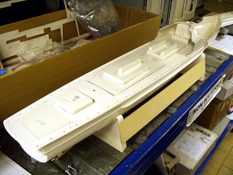 |
|
|
 |
We re-studied the kit box photo and concluded that as the deck is at right angles to the hull walls with NO lip, edge, ridge or anything! The model depicted on the box must therefore be a pre-production model or at least a heavily "modified" or "corrected" model. |
|
 |
|
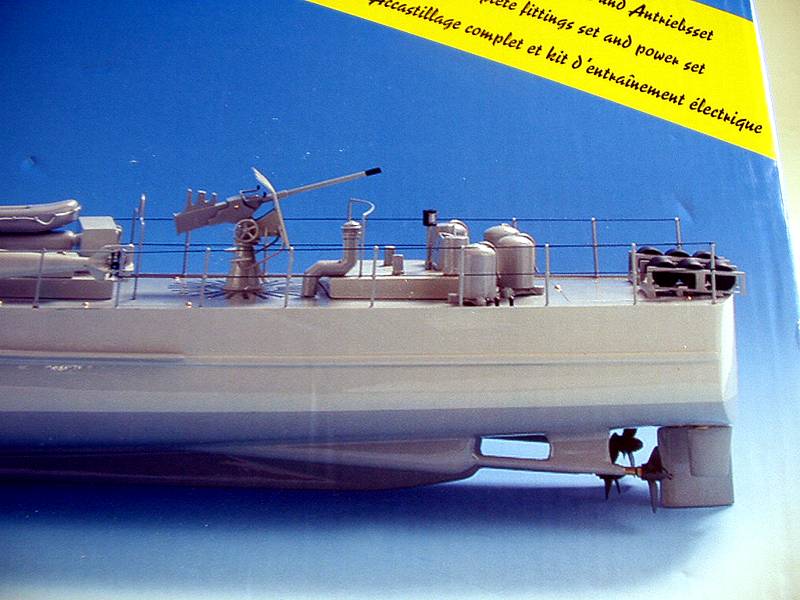
Looking into this a bit further, another
search on the internet. " Robbe S 130 " yielded the best results and one
site in particular ..... http://www.modellbauflotte.de/sboot.htm These photos show a production model and the "lipped" deck joint can be clearly seem... if you look hard enough. |
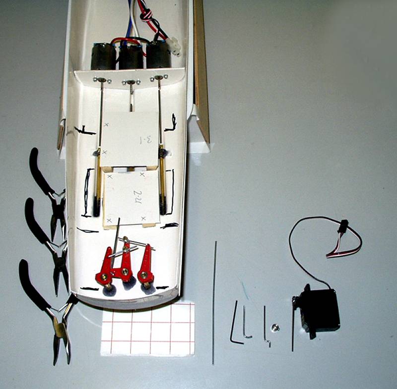 |
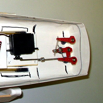
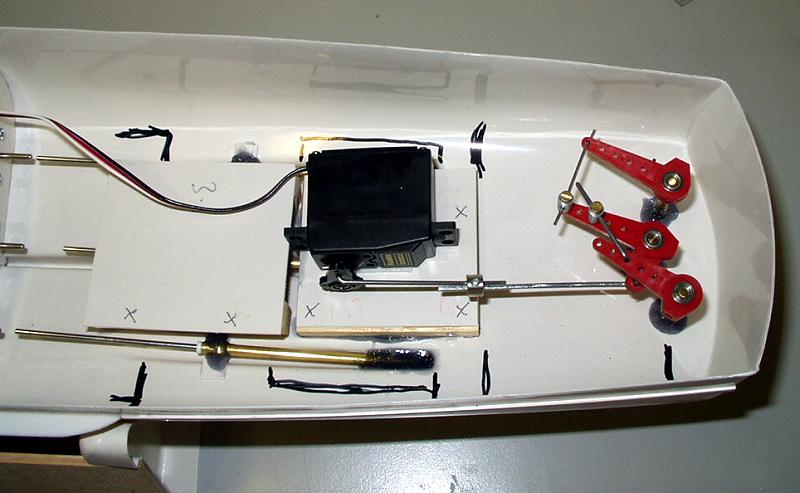
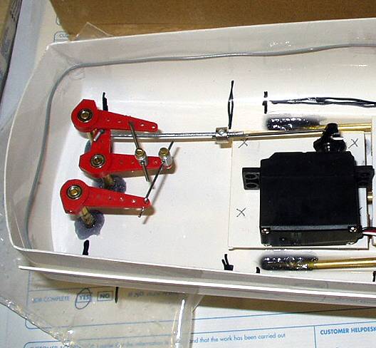
Ok so now we know how the deck will be fitted, lets get on with finishing off the engine and navigation rooms. 2 platforms need to be fitted, one for the rudder the other for the speed controller. First to go in is the rudder servo. It's mounted on it's side and fixed permanently down on it side with double sided tape. I centralized the servo by hand ( move end to end and judge to mid point ) and cut down the arm as per instructions and screwed it on. |
|
 |
As the servo will be glued
down permanently, retrospective adjustment or replacement of the output arm
is going to be a 'real bitch', especially if trying to work through a very
small hatch. Glad I won't have to do it! Also, as it is going to be
'fixed, once for all time', I always help double sided tape with a drop of
superglue as I have found that these tapes usually come adrift after a
while due to moisture entering the boat. |
|
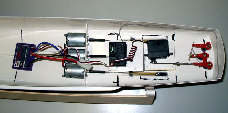 |
Next the instructions say that the Electronic speed controller and Radio receiver are mounted next to each other on a raised platform... call me 'old fashioned' but I've always tried to keep the two as far away as possible in all my boats to help prevent electrical interference. Having said that, this Robbe Electronic Speed Controller (ESC) is a very impressive unit! |
|
 |
Time to bite the bullet
again, the indicial radio test! |
|
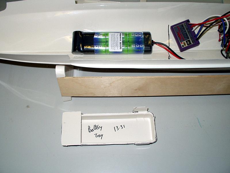 |
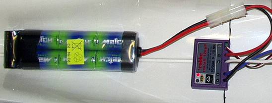
There is no final position for the battery pack in the instructions as the weight of the battery can me moved about to obtain the best ride of the boat at speed... "Rubbish! You tell me the best place to fit it. You're the ones that designed the model and make very precise recommendations of what to buy and fit!" Yes, as you can tell I'm getting a little nervous at this stage as a lot of Very expensive equipment is going to be connected up to a very powerful battery. (For non electric boaters out there, just a relatively few NiCad cells, wired correctly will start your car engine!) | |
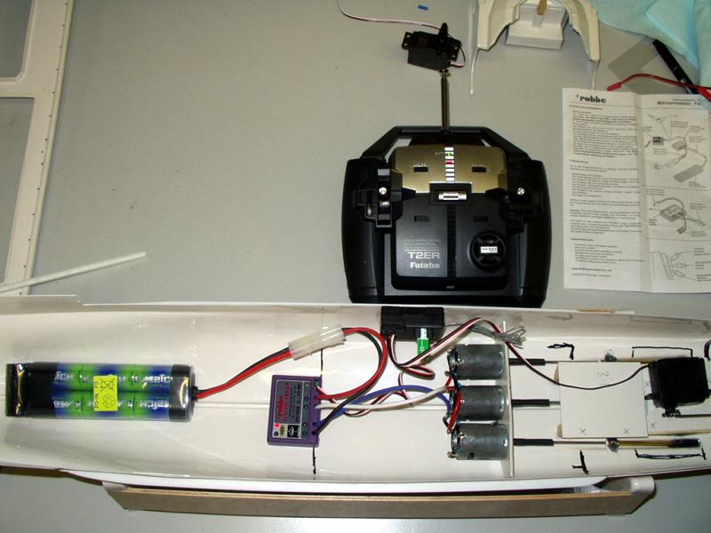 |
First to be tried out is the rudder set up. I temporarily wired up the receiver to 4 AA batteries in a holder supplied with the radio gear. Always remember to switch on the transmitter first when running and radio controlled model, it prevents any spurious electrical signals driving your receiver and servo crazy! | |
 |
As you can see, when the radio was powered up
the servo decided that mechanical centre was no where near electronic
centre and shot off the rudders into a hard turn to port... "Damm! That
servo Arm is going to be a real bitch to get off and repositioned."
.....Where have I read this before??? I cursed myself for such a simple mistake but how was I going to adjust it now? This evolved quite a bit of head scratching, followed by painstaking removable of wood splinters from under my fingernails! ( That line nicked from Brian Pratt's article QUEST in this months Model Boats magazine [September 2003] - "Plagiarism, the most sincere form of flattery!" ) |
|
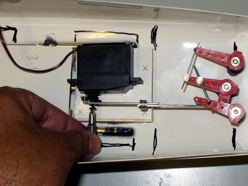 |
In the end, a small crosshead HEX screwdriver bit use utilised - not too hard after all. | |
 |
IT WORKS !!!
( 2Meg video - QuickTime required ) |
|
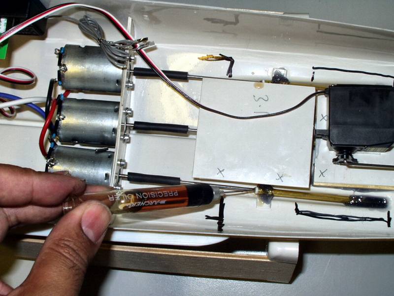 |
Next job was getting the motors working. Here I have replaced the temp couplings with the kit's rubber couplings. I decided to trim the prop shafts back by 8mm which would allow the couplings more freedom. All bearing are lubricated, shaft and motor. | |
 |
Next the motors! I read and reread the ESC instructions. After an hour of not making any sense of them I concluded that I can read neither German or French so I then read the English version! Basically, turn on the Transmitter and connect the main battery! | |
|
|
After a stiff drink and a
visit to the men's room ( physical preparation for this next big
step! ) I summoned up all courage and plugged in.......! After a few
seconds I opened my eyes, pulled my fingers out of my ears and ginererly
sniffed the air. |
|
|
Now there is a theorem that amongst us technical types that states that: 1. Wires are multi coloured because, if or when they turn black, you can tell which ones have a problem. 2. Electronic Transistors and IC are black to save time when they burn out. 3. All electronic devices have smoke sealed inside - once this smoke escapes, they no longer work! It's called the "Oh bugger! law" --- Try it for your self! |
||
 |
Hey a red light on the ESC,
that's what the instructions said would happen! Good stuff !!! This ESC is
actually very easy to set up, in fact the easiest I every used. |
|
 |
It's ALIVE!!!!
( ....and I bet it makes you laugh! ) |
|
 |
I revisited the rudder
linkages and found as usual the servo arm doesn't align perpendicular to
the servo at electronic centre thus introducing parallax error. |
|
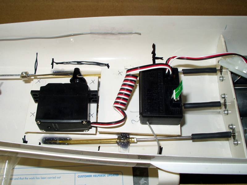 |
In the end, I decide that I would mount the Receiver on the platform near the rudder servo and mount the ESC on a scratch built platform the other side of the motors, near the batteries. This keeps the power and electronic sides of the electrickery as far apart as much as possible. Studding the web sites above you can see these builders also had the same problem. |
|
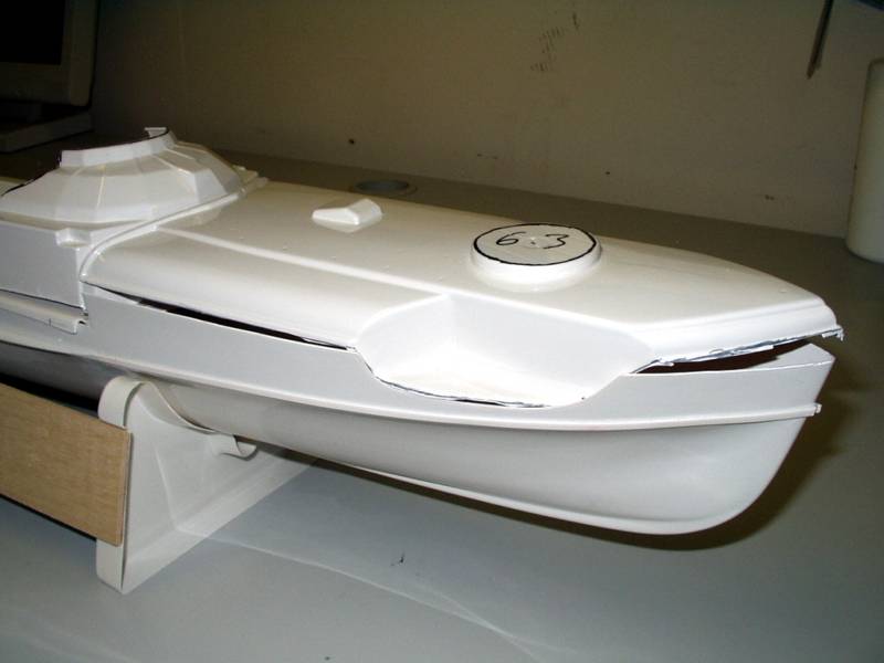 |
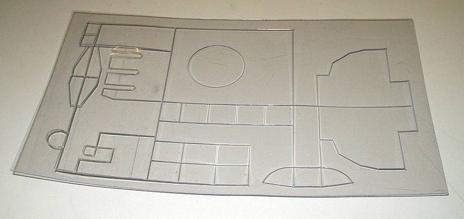
I'm still on entirely happy with the deck fitting arrange meant because not that I've decided what to do at the back, the foredeck / forecastle is going to be even a bigger problem. This is the foredeck cut right on the cutting lines. Just look at those gaps!!! That is going to take a lot of bending and filling as this is the most visible part of the entire boat. |
|
 |
As some stage soon painting
will have to commence. Before doing any painting, I usually like to
have as many sub assemblies completed as possible, spray paint all the sub
assemblies and complete the model by just joining the sub assemblies
together. This helps prevent damage to paintwork during building. |
|
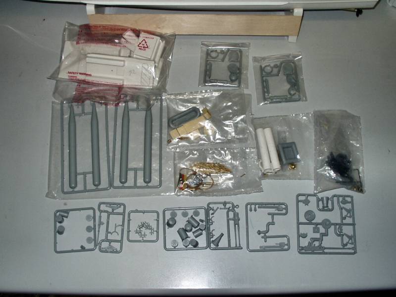 |
First I would have to find the components. Robbe have a curious was of bagging up the components. It seems they bag up the bits according as to where they fit on the model, not in the assembly order - you soon have every bag open with just one or two bits removed from each. |
|
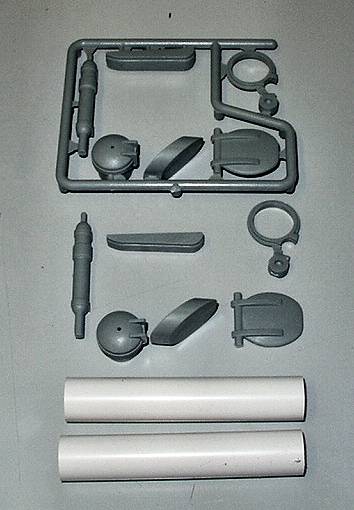 |
I guess these are the bits needed.... | |
 |
.... but there is no clear picture how precisely they are to be fitted. They also didn't fit very well and needed quite a bit of sanding and cleaning up! |
|
 |
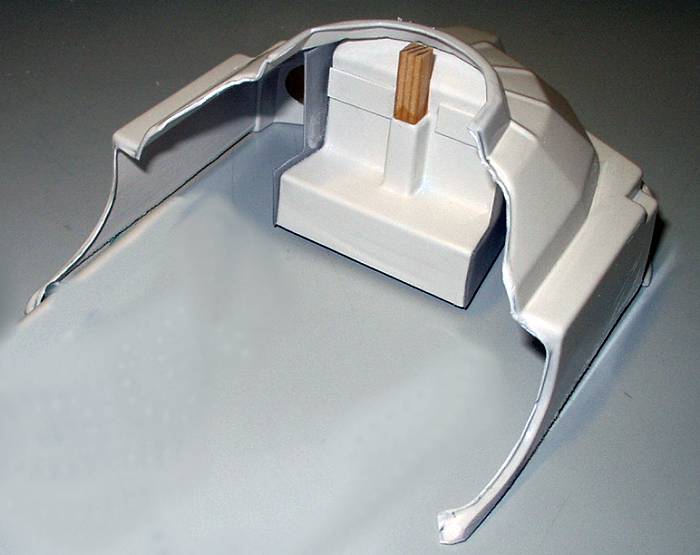
While building the control "dome", some bits have to glued to the central platform in make it more "functional". I search around for bits "5.3" for ages. They are two side panels that watch the centre consol.. or so I thought. I search through the box, through the scrap / cut off bag, under the box, on the self and under the desk - nothing. "Bother! They're missing from the kit. I'm gonna have to make them myself...... and what this windscreen martial is for, there's no windscreen on the model?!??!!" That's when the penny dropped. For a reason only be known to Robbe themselves ( or maybe someone on the assembly lines was having a laugh ), what I believe should be white ABS plastic turns out to be clear sheeting!!! It's all going to be sprayed grey anyway, so who knows why. |
|
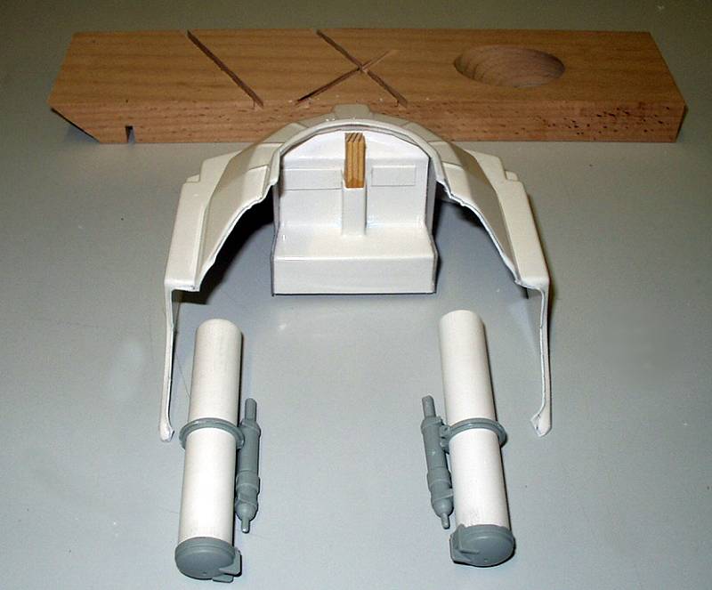 |
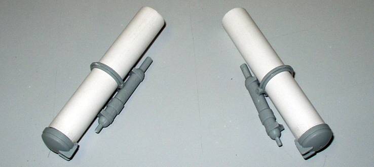
The tubes made up and the holes cut in the front bulkhead. The strange shaped wood in front is a handmade gift from a friend, it's one of those clever wine bottle balancers... it's now my drilling board! | |
 |
Test aligning from the front. | |
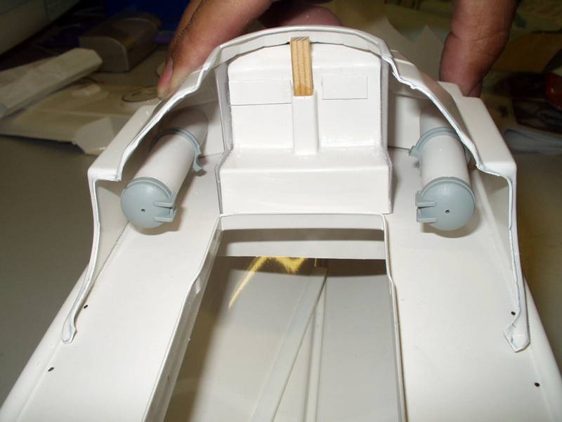 |
Test aligning from the stern. | |
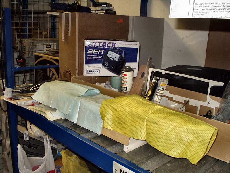 |
The S130 Back on the self and disguised to prevent
allied attack. |
|
| I know I'm moaning a bit about the kit but I do like it and having a lot of fun building it. But it's not a cheap kit and certain parts like the deck and forecastle joining problems must have showed up in pre-production but nothing seems to have been done to correct the design or make assembly easier. When you have CNC machined moulds and extruded parts and then get them wrong.... sorry Robbe you have NO excuse. Interestingly, Robbe are the same company that have made the best model boat hull I've seen, the Scarab ( also used on the Little Devil & Lightning ) | ||
|
Well all this just my opinion, but what do I
know! |
||